ENGINE
[HATCH SHOCKS] [455 / 403][HOT START PROBLEM] [CARB
REBUILD][CANISTER]
[ZDDP]
[THROTTLE] [ACTUATOR][SPARK PLUGS] [COMPRESSION
CHECK][HEADERS][DIP STICK]
[REMOVAL]
[SENDER] [HEI] [SERPENTINE]
[BELTS] [FENDER / SIDE VENTS] [COPPER]
[CLUTCH][HEAD GASKET]
[ALT. LIGHT] [DIM ALT LIGHT][ALT. SPACER]
[WIRE DAMAGE][THERMOSTAT]
[BROKEN BOLT REMOVAL]
THE CORRECT FIRING
ORDER

Click below for a higher Res. Picture
http://www.gmcmhphotos.com/photos/showphoto.php?photo=7034
FIRING ORDER - Maintenance Manual X-7525 Figure 50 on page 6Y-50 is
incorrect! The # 3 and #6 posts in the distributor are reversed. Note:
all
other figures in X-7525, X-7625, and X-7725 are correct. ROB
 To search for a
topic on this page
type Ctrl+F and the key word.
To search for a
topic on this page
type Ctrl+F and the key word.
ENGINE HATCH COVER GAS SHOCKS
I have added some pictures showing
the props in more detail. I purchased the part from McMaster-Carr.
http://www.gmcmhphotos.com/photos/showgallery.php?cat=3061&ppuser=56
P/N 9416K192 are the gas spring 30lb force
P/N 9416K86 are the end sockets
P/N 9512K73 are ths ball mounts
I used aluminum angle to mount.
Measuring from the rear it is 26" to the ball on the hatch and 11 1/2
on the floor
I don't use a hinge, the hatch fits into a slot in the front. If
I need to remove the hatch I just pop the gas springs off the ball and
lift out.
Hope this helps
It eliminates the embarrassment of explaning why there is a knot
on the back of your head and the inprint of the air cleaner wing nut on
your forehead
Jim Wagner
**********************
I put some pictures up on my website that I took at the rally in
Iowa. I hope you don't mind. I'm going to place an order
with McMaster-Carr today
for the parts.
http://www.palmbeachgmc.com/hatch.html
Richard Waters
Supplementing the September 2007 issue
of GMC Motorhome News, Sam Carson of Indian Harbour Beach, Florida, has
advised that new American Petroleum Institute (API) SM Service
Category oils contain a significantly lower amount of zinc dialkyl
dithio phosphate (ZDDP) than former API SL, SJ and earler API Service
Category oils. The ZDDP component is an important additive for
the lubrication of flat lifters and cams in GMC Motorhome engines.
Carson is aware of at least three GMC Motorhome lifter and cam failures
after owners changed to SM oils, which are the oils most retail outlets
currently stock. Our search of the media indicates similar
failures in other engines manufactured prior to the 1990s when roller
lifters were installed in almost all new large-block engines.
The ZDDP additive has been significantly reduced because the
Environmental Protection Agency (EPA) claims it can poison modern-day
catalytic converters. The petroleum industry is conducting tests
to
either prove or disprove this claim.
We have long recommended Mobil 1 for GMC Motorhome engines, but many
owners do not want to pay the price of synthetic oil. Synthetic
oils have not been reformulated and meet either API CF or CJ-4 diesel
engine Service Category specifications along with API SL or SM Service
Category specifications. These oils maintain old levels of ZDDP,
and will adequately lubricate the lifters and cams in GMC Motorhome
engines. Other non-synthetic diesel engine oils that meet API CF
or CJ-4 Service Category specifications also have adequate levels of
ZDDP. Chevron's Delo is an example.
Since all GMC Motorhome engines were manufactured with flat hydraulic
lifters, API SM Service Category oil "should not" be used when changing
oil unless it also meets API CF or CJ-4 diesel engine
Service Category specifications. To be on the safe side, use
Mobil 1 15-50. It is expensive, but often can be purchased on
sale at discount auto parts stores and at Wal Mart.
Cinnabar Engineering, Inc.
=========================
GMC Motorhome News is available at:
http://www.thegmcmotorhomepeople.com/news/
BLOWN HEAD GASKET
SINGLE HEAD REMOVAL - WITHOUT REMOVING
THE INTAKE MANIFOLD
http://www.picturetrail.com/gallery/view?p=999&gid=1206059&uid=649762
Your engine problem sounds like the failure I experienced last fall
returning from Nashville.One cylinder measured 10psi
compression and a oily spark plug.One third of the exhaust valve
burned away in 10,000 miles since complete engine rebuild.
Only one head was removed and another head installed in under 8
hours
Repair was done in my garage.Required one intake manifold gasket
replacement
on the left head Lawrence
BLOWN HEAD GASKET - REMOVING THE
INTAKE MANIFOLD(7/16/05)
Examined the plugs, good Color. Then a compression check showed 150 for
all the cylinders except 6 and 8. They were at 30 pounds.
Removed intake including carb disconnecting as few vacuum lines as
possible. Then disconnected exhaust pipe so that themanifold came out
with the head. Much easier to remove manifold bolts on thebench.When we
go back together I will install the manifold on the pipe loosely.Then
mount the head and torque bolts to specifications. Then using the
twoend bolts I will attach the manifold to the head loosely. Then
insertexhaust manifold gasket between head and manifold, install the
rest of themanifold bolts and torque to specifications. And so on and
so on. If I wasonly removing the exhaust manifolds I would remove the
wheel well liner and
CANISTER REMOVAL
Names have been removed to protect the Guilty
I just unhooked the line at both ends and capped the TBI line.
When I went for my smog I replaced the carb, installed the line and
pushed the line over a cap on the carb. I didn't want any extra
HC present. Passed with flying colors. The canister is only
there to catch evaporation. It is not part of the tank venting
system.
last spring I experienced the symptoms that you have and I
disconnected the line from the separator valve, plugged the port on the
carb and ran a line from the separator valve down along the frame to
below the bogie wheels. I do not have to have my vehicle
inspected here in Santa Fe but if I should move I can easily reconnect
it.
----------
FENDER / SIDE VENTS FOR ENGINE COMPARTMENT
I have the Caspro Stainless Steel vents on the coach. Yes they do
work and work very well. Anything that you can do to remove the
heat from the engine compartment is good.
I can stand next to the coach and the air flow just pours out.
Along with Caspro, Jim Bounds sells a less expensive unit that works
very
well also. Some people have also used the vents list on page 544
of the West Marine catalog. Model numbers 375477 & 386559
have
approximate the same dimensions as the Caspro unit but are half the
price.
You can go to www.westmarine.com.-- J. R. Wright
***********************************
I've been looking at several photos of coaches that have been
"updated" for ideas. That includes photos of the inside and photos of
the outside. I understand that a big concern is heat in the engine
compartment. Based on my unrealistic research it appears that about 45%
of you may or may not have added fender vents (how's that for a neutral
political statement?)
Based on the percentage of you that have added vents it would appear
that there are several varieties and styled implemented with the Ragusa
not being quite as popular as I would have imagined. So, I set about in
search of some options and came upon several at West Marine.
Now, the Silver Lady is in the shop undergoing a lung transplant so I
can't go out and measure her cavity. I'm turning to the next best thing
and seeking an opinion via this illustrious body (and you have to be to
own a GMC). The question is, will this vent fit? It's takes a 3 5/8 x
12 in. cutout.
The URL is too long to put into a text document. You can, however, go
to http://www.westmarine.com
and follow the links for "Ventilation" /
"Exterior Vents" and seeing what I'm talking about. It's on the right
hand column. The caption says "SEAFIT VENTS | Stainless Louvered Vent -
13"L | Only $21.99 USD"
Looks descent. Good price. BTW, I did find the type like is on the
Cadillac SUV but I don't want to pay $230 for a chrome version when
this may do. Byron Songer
******************************************
Back in 1990 I got some nice looking stainless steel vents and put them
into the side. I must say that when you stopped you could
certainly feel a lot of hot air coming out of them. However, I
never knew if they did anything when driving down the road.
A few years back I installed some of Darren Paget's insulating blanket
pads under my floor and engine box cover. That really deadened
the noise and the floor was much cooler. However, I then
found that I was starting to get vapor lock which I had never
encountered in several previous years.
An examination of this new problem revealed that the fender liners have
a "standoff" where the screw goes up into the floor above the
liner. If you examine this closely you will see that the liners
have a "scoop" on the front which brings air up and over the liner and
down to the back. This is something like an airplane wing shape
and the air going over the liner (think wing) is going a farther
distance in the same amount of time as the air under the liner (think
wing). This creates a low pressure zone at the top which in the
case of a wing gives lift. I feel that in the case of the fender
liner the lower pressure will pull the heat from the manifolds which
are adjacent to the wheel liner. When I blocked this passage with
the insulation it no longer pulled air over the liners and air from the
motor box so I started to experience overheating and vapor lock.
My solution was install some louvers in the wheel liners (house
foundation block vents) and also to put some scoops under the bumper
(house rectangle to 4" round duct adapters from Home Depot. The
ducts have some aluminum dryer hose that goes to the back top corners
of the engine box to force cool air into the top of the box which in
turn pushes out the hot air.
All I know is that it has worked extremely well. I live in the
hot southwest and often travel in 120 degree temperatures while pulling
a toad and have never had any vapor lock since doing my modifications.
You can see this at:
http://www.gmcmhphotos.com/photos/showgallery.php?cat=3093
They are not in the original order but there are not many
pictures.Emery Stora
Here are Bert's wheel well holes
http://www.gmcmhphotos.com/photos/showphoto.php?photo=8756
SERPENTINE BELT CONVERSION
Yes I have the serpentine setup on my coach. (Now has been removed 6/29/05)
I had a few problems with the a/c compressor pulley. I was shipped a
pulley that would rub against the body supporting post. This led to
bearing failure and clutch failure while on the road. After I
complained about it I was asked to use a shorter belt and given the
part number. A new pulley was shipped, shorter than the previous one
but once
installed, no way to pull it out without damaging the groove ring,
I shipped it back. I ended up machining a pulley and using the ring
from the first pulley. I also had some alignment problems with the
alternator/power steering units mainly due to a missing bracket. Emery
helped out on this on the parking lot in Mt Hood on the GMCMI
rally
Water pumps: I did a study on water pumps and the reverse
flow and had posted on photopoint. I found out that with the reverse
flow I was only getting 2/3 efficiency. My solution to this was
replacing the thermostat with 170. For those interested, I would not do
it again. I would not go back either because its working fine and I
spent too much time getting it to work. Manny
Jim Bounds
I tell ya guys, you know when you ever make a
decision and get off of the proverbial fence--- there will always be
someone on the other side that will not be happy with your move but
hey--- crumbling cookies! After talking to many about this both
professionals, engineers and even people I respect an opinion of---- we are not going to reinstall the
serpantine belt system on this motor. I did not make this
decision lightly and if I can bore you for a minute, I'd like to tell
you why we are doing this.
(6/20/05)
********************************************
The best spark plug wires are Dick Paterson's(http://www.paterson-gmc.com/wire.htm).
Spiral wound wire cores have minimal resistance compared to
the graphite core OEM types. Spiral winding "chokes" RF
interference. For the price he charges, you couldn't build
your own from the "universal" kits in JEGS, etc. My $.02
Patrick
ENGINE REMOVAL
OUT THE TOP
FRANK CONDO'S HOIST
http://www.gmcmhphotos.com/photos/showgallery.php?cat=3180
YIPPEE, OUT THE TOP ON A 23
http://www.gmcmhphotos.com/photos/showgallery.php?cat=3954
OUT THE BOTTOM
IN AND OUT THE BOTTOM
Here's how to put it back in. Removal is sorta the opposite. :-)
http://www.gmcmhphotos.com/photos/showgallery.php?cat=3950
You will still need a gantry from which to suspend it, though it need
not be
as tall as the manual shows -- just tall enough for the two winches to
operate beneath it. The gantry should have two hoist trolleys and
the hoist
must be strong enough to individually support the
engine+transmission+final
drive -- certainly no less than 1-1/2 ton for safety. Position
the stronger
hoist at the forward mounting point, just forward of the CG (~3" fwd of
the
forward carb mounting bolts).
You'll need to get the coach 30"+ off of the ground.
If it weren't for all the wires & hoses, it would be an easy job.
I spend
more time trying to find & correct the leaks than anything else.
KenH
THE ONE SECOND ENGINE REMOVAL - CHARLES
how not to do it ;>)
http://community.webshots.com/album/34227045RGnTKM
REMOVE THE CLIP
PICTURES - CLICK BELOW
http://www.gmcmhphotos.com/photos/showgallery.php?cat=5924
I first raised and supported the coach about 6" higher than normal ride
height. Then I removed the following (text from Jim Wagner's post):
> I first removed bumper, grill, valance, inner fenders, battery
tray, air
> pump, steering box, brake lines, gas lines
and gas filler tube from
> tanks, emergency brake cable, misc. wires + normal wires and hoses
> needed to remove motor through floor.
Also unloaded the torsion bars, unbolted exhaust system from
manifolds, discharged A/C system and disconnected the lines from the
evaporator, disconnected speedometer cable and transmission shift
cable.
The 12 bolts that connect the subframe to the intermediate frame
were removed. A low
4-wheel dolly was positioned under the frame. Wood blocks were stacked
on the dolly so there was about a ¼" gap between the wood and
the frame. The front of the frame was supported with a jack while the 2
frame-to-body bolts were removed. The jack was then lowered and frame
dropped down the ¼" so it was clear of
the body. The frame will slide in the side rails as it is
pulled forward. Have wood blocking under the rear of the frame so when
it comes out of the side rails it will be
supported. Joe Bertrand
*****************
I removed my front frame with complete drive train today, here is
what I did.
1. Fill air bags.
2. Put jacks stands behind six frame bolts where frame will
separate
3. Raise to about 23 1/2 inches to bottom of front bumper.
4. Remove grill.
5. Remove valence under grill.
6. Remove bumpers from frame.
7. Disconnect front and rear batteries.
8. Remove inner fenders.
9. Open pet cock on radiator and drain.
10. Disconnect radiator overflow hose from overflow tank.
11. Remove battery.
12. Remove rear battery cable from top of cross member & solenoid
13. Remove air conditioner compressor, it will hit body support
14. Drain freon and disconnect hoses from evaporator housing.
15. Disconnect hoses from windshield wiper motor.
16. Remove battery tray.
17. Disconnect oil filler from top of grill opening.
18. Disconnect air hoses from compressor & remove compressor
19. Remove hoses from steering box.
20. Remove steering box from frame and tie-rod end.
21. Remove lines from master cylinder and plug hose in master cylinder.
22. Disconnect rear brake line from brake block behind driver-side tire,
and remove electric wire.
23. Unbolt rear brake line from frame.
24. Disconnect bracket holding gas line on cross member.
25. Remove rubber hose on gas fill line.
26. Remove bolt on emergency cable at Y fitting and pull cable
through frame to front.
27. Unbolt gas vent hose.
28. Remove rubber gas hose behind cross member; plug hose.
29. Remove gas tank to canister hose on top of cross member.
30. Unbolt gas tank vent line from cross member.
31. Open engine cover; remove bolt, holding two cables to cruise-
control transducer.
32. Remove lower cable from transducer and vacuum hoses.
33. Remove air cleaner and disconnect two water hoses to rear.
34. Disconnect wires for alternator, oil switch, water switch,
distributor,
starter (2), cruise control,
air conditioning.
35. Remove throttle cable and vacuum hoses.
36. Remove transmission shift cable
37. Remove oil filler tube to engine
38. Remove dipstick to coupling
39. Loosen gas fill tube from body
40. unload torsion bars
41. Support front of frame & remove 1 2 frame bolts
I used an engine lift on front
cross member to hold frame
42. block rear wheels
43. remove 2 front body mounts
44. when pulling frame forward lower frame so steering box mount will
not hit fiberglass
45. remove wheels
46. To pull frame forward I backed my truck about 6 foot in front
of the
GMC & used 2 come-a-longs from
the rear bumper to each side of
the GMC frame Bill
-------------------DIPSTICK REPLACEMENT
Anyhow, with time to relax and listen to the wind in the pines and the
thunder approaching, I decided to check
the oil. NO reading, but it felt funny going in and I suspected
the bitter truth. Threw a quart in just to be safe, and after
making our way home the next day, I confirmed my fears: a rusted-out
broken dipstick tube. A call to Cinnabar got a new lower tube on
the way (~$14 + shipping), and I set in to pull the old one.
After several false starts, this is what worked for me:
1 Remove left wheel, wheel well, and exhaust manifold for
access.
2 Take a large (10") pair of Vise-Grips(R) with
good teeth on the ends of the jaws, and drill a 1/4" hole in the
body of the tool about 1/2" behind the jaw pivot rivet. (Avoid
jaw, springs, etc.)
3 Clamp the tool tightly on the broken
dipstick tube. Go low enough to get solid metal to bite.
4 Using a small slide hammer with a hook end
(J.CWhitney Dent Puller, about $25 a few years ago), hook into the hole
in the Vise-Grips, align as straight as possible, and slide-hammer the
sucker outa' there!
5 Select a crow's foot socket that just
fits
over the new dipstick tube. Slide it down to the expanded collar
of
the tube, insert an extension bar, and use to hammer the new tube into
place.
"I love it when a plan comes
together!" HTH.Rick Staples
My advise would be to push the stub on thru. Run a long piece of
bailing wire down thru the hole where the tube was and out the oil
drain hole. Did I mention that you need to drain the oil?? Then with
a small punch push the stub on thru and it will slide down the wire and
into your hand. How's that for an alley mechanics
trick.<G>....................Terry
HOT
START / STARTER PROBLEM
>Good time to start up an old discussion...... This might be an
urban myth on the GMC. The problem is usually bad battery cables,
grounds and batteries, not the starter..... I have not seen proof that
this exists on the GMC.
Read here for grounding problems
http://www.gmcmotorhome.info/chassis.html#GROUND
gene
-------------
I would agree that this is a myth.
I have no such shield on my starter and today I stopped for lunch
at 100 + degrees and the GMC had plenty of starter power on HOT!
restart. Additionally, I have headers and had just driven
it over the San Jacinto mountains and it was hot. I think people
with this problem have electrical problems as you have described. A
heat shield on the starter shouldn't be necessary and is not addressing
the real problem.Phil Swanson
-------------
I also had a hot start problem. Had the starter rebuilt
(rebuilder said it wasn't in bad shape to begin with)
Ran a new #2 ground wire from the battery to the motor and replaced
a group 27 battery with 650 cc amps with a new group 24 battery with
1000 cc amps. No more hot start problems. Don't know which of the
above fixed it (?) I also bought the heat shield for the starter and
its been in the blister pack on my bench for over a year. Dick Missett
COMPRESSION CHECK
Was the throttle wide open during this test - it should have been.
I like to remove all the plugs - that way the engine spins easier and
faster - pull out the plug to the HEI.
But a compression test is not the final say - just a guide to engine
condition - What you should do next is a "Compression leak down test /
differential compression gauge". it's only slightly more complicated.
here's how I do it.
I beg or borrow a leak down tester from good machine shop or speed shop
-
I give then a deposit which is equal to the replacement value for their
tool - just in case.
. do NOT remove all spark plugs
. remove the connector from the HEI
. remove the distributor cap
. stuff a rag in the oil fill neck
. remove the pvc valve
. remove air cleaner
. mark the base of the distributor with the location of each plug
wire
. turn the ign key to position the rotor to just a wee bit past a plug
wire position (this will be about TDC for that cylinder) &
both
valves will be closed.
. the leak down tester needs an air supply input of about 120-140 lbs.
each cylinder is pressurized with a known amount of air pressure
and the
second pressure gauge indicates the amount of leakdown (lower
pressure
thru a standard orifice build into the gauge). The differential
on our
engines should be greater than 80%
(source pressure vs leakdown
pressure) Brent Covey - correct me if my
percentage is too low.
. I leave the other spark plugs in to help prevent the engine
from
spinning due to the 120lbs of air pushing on a cylinder.
. Now here's the good part -
listen at the valve cover PVC hole for air (blow down from the
cylinders)
listen at the tailpipe for air (exhaust valve leak)
listen at the carb (intake valve leak)
. with only 70k on your engine - you may only need a valve job
hope this helps
Been there (a number of times)done that (more times then I care
to admit)bought the tee shirt Pete
FRONT ENGINE MOUNT
You can get the 1972 Eldo. front engine mount, and the right hand shaft
and bearing support from Maximum Torque Specialties http://www.mtscadparts.com/
Jerry Lader
CARB NUMBERS
The carb number is on the left side of the carb, on the flat surface
above the throttle shaft. The number will
run vertically, and there will also be a number which is the day of
the year and the last digit of the year it was manufactured.
73 & 74, 455's 7043254
75 & 76, 455's Federal 7045254
Calif. 7045554
77 403's Federal
17057254 Calif. 17057559
78 403's Federal
17058254 Calif. 17058559
the parts list for the Quadrajet carb used on the GMCMH.To view, go
to
http://www.gmcmhphotos.com/photos/showgallery.php?cat=4685&ppuser=517
Bob Drewes seSD
Carburetor
Rebuild
SEMINAR BY FRANK CONDOS
http://www.gmcws.org/Tech/quadrajet/
I had mine rebuilt by A & G Carburetor in 1996, which is
located on the West side of Chicago in Oak Park. They told me
that after their overhaul, all I would have to adjust was the idle
mixture and idle speed. We mounted it back on
the engine and never made any adjustments to it. I had stripped
the bowl threads for the filter nut and they replaced the bowl.
The rebuild included epoxy sealing of the bowl plugs, leather
accelerator pump, needle and seat (plus a spare needle and bowl gasket
for your tool box) and replacement of the choke pull-off. They
also check the throttle plate shaft for wear/leakage and bush it
if needed.
I sent it via UPS Monday morning and had it back via UPS Friday
afternoon that same week. The carb came back so clean I called
them and asked what they sprayed on it to make it look so new.
Their response was they use an eight step washing process and nothing
was sprayed on it.
Not knowing of them other than seeing their ad in the GMC Motorhome
Marketplace magazine back then, I called and talked to them 3 or 4
times, to satisfy myself that they knew what they were doing. Each time
I was more impressed than the previous conversation. There was no
BS, if you know what I mean. They certainly should be able to tell if
your card has the right components for the Motorhome, and if
not bring you up to speed.
Back then they charged $138.75 for the overhaul, $15.89 for the
choke
pull-off, and $40.00 for a replacement bottom bowl. Call them and talk
to
them - 708-386-9804.
Paul Bartz
Carburetor Throttle Adjustment
You can adjust the final throttle cable travel by simply
bending
the accellerator pedal linkage under the dash. Yes,
just bend it. While I removed the pedal assembly to fix mine some
years ago, you can do it in place without removing it after you
unhook the cable from the pedal (hindsight). There is no reason
to buy a new cable. I also had the same prob with the
cable/bushing end at the carb = nonexistent - got a nylon bushing
close to the same size at the local hardware & massaged it so it'll
fit. Ritch & Betty
---------------------
"You can also adjust the throttle slack by just
using a small fishing line split lead sinker. Crimp it
on the throttle cable just above where it connects to the pedal.
It will take up some slack on the cable. If really bad just
use two sinkers. You might find this easier than trying to bend
the pedal the right amount."Emery
GMCs are known for the gas peddle hitting the floor before the
carburetor is at wide open throttle (WOT).
Sometime,
remove the engine hatch and look down the carburetor throat and see if
the "big boys" open up when your gas peddle is WOT. (you will
have to open the choke flappers. Probubly not, so
here is what I call the Emory-split-shot-fix for this problem
http://www.gmcmhphotos.com/photos/showphoto.php?photo=30923
There is so much slack in the acellerator linkage, it might just be a
good idea to do this mod (just in case).
--------------------
I did the same and then heard that Ken Frey sells a replacement.
IIRC, the
nylon bushing should be 1/4" ID. I put it
on a 1/4" screw between two
washers and tightened down a nut on top of that. Chucked the
screw into an
electric drill and spun the bushing on some 300
grit sandpaper. After maybe
10 minutes of the sand/fit cycle, I had a properly sized
bushing.Patrick
THROTTLE LEVER ACTUATOR - REPLACEMENT
I had a problem that my 1978 GMC MH engine (403) would die when I
exited the interstate and arrived at a stop light. It would start up ok
and run fine until the next stop sign and die.
I discovered that the vacuum operated throttle lever actuator was
leaking air. Its purpose is to increase the idle speed when the A/C is
on.
A simple bypass is to plug the vacuum line and increase the idle speed
about 200 RPM's, but the increased idle sometimes leads to dieseling
when ignition is turned off.
After weeks of searching for a replacement I was eventually refered to
a place in Texas that rebuilds them.
REBUILDERS SPECIALTY INC. 15049 Valleyview Rd. Forney, TX 75126
972-564-4141
They were very helpful and rebuilt my Throttle lever actuator for $15
(just like new). Much better deal than finding another old unit
with
aged diaphragm. John Wolever
REPLACE OIL COOLER HOSES AND EMERGENCY FIX
I always tell new owners that if the lines are 10 years old or of
unknown age, replace them. Lines that
look good break all the time and can cause
disastrous damage to the engine within just a few seconds, sometimes
accompanied by a fire when oil hits a hot exhaust manifold. See:
http://www.gmcmhphotos.com/photos/showgallery.php?cat=4028
Bob Burkitt
OIL COOLER HOSE REPLACEMENTS (8/13/08)
J.R. Slaten who is a GMC owner makes and sells the stainless
steel braided hoses for both the 455 and 403 engines.
They are first quality, bulletproof and should never have to be
replaced ever again. He is a member of the GMCNet and you can reach him
at jrslaten@aol.com and his
phone number is 502-363-3011.J.R. Wright
http://www.bdub.net/jrslaten.html
-------------------
-
Theres a few things to pay extra close attention to-
All carb kits and parts within them are ordered by looking them
up relative to the carb number stamped into the carb body. This
number will start out with "70xxxxx" or "170xxxxx" and you'll need that
to order the goodies for the rebuild.
Most GMC carbs will have very little wear as this is something
that occurs more in high city traffic mileages, not just zooming down
the highway.
Every time you encounter a black coloured foam float, replace
it. Some GMC's use a brass one which you can shake and see if its
pinholed and allowed liquid inside. Most are fine.
ALWAYS buy a new vacuum break diaphragm, this is the little
bellows thing that pulls the choke open, located at the passengers side
front of the carb. These are the #1 failure in carbs, and cause
flooding and hard starts when they fail. A used one is OK to use, but
make sure you have a spare anyhow, and carefully check that it holds a
vacuum and pulls the choke open when
vacuum in applied.
Never remove the throttle plates or shafts or choke
plate/secondary air valve unless you are replacing them, as the screws
often break off and are in a position if they fall out the engine will
inhale them, which is bad news.
The vacuum break adjustment is altitude sensitive. The kit
instructions do not make it clear how its adjusted, but the essence is,
it should open about 3/16" when the vacuum break diaphragm has vacuum
applied to it. This is approximately the distance the little groove
embossed into the choke flap is wide. Once its on, you may need to
fiddle a little with this setting, it needs to open less at low
altitudes than higher ones.
Main jets need a PERFECT fit screwdriver to remove them. They
can strip and tear up with the wrong one, so get a really tight fitting
screwdriver for them. A sharp blow to the handle of the screwdriver
with a light tool will usually aid in breaking them free, they like to
get stuck in there.
Retain the original GMC main metering rods, they're perfect for
the GMC. Jets can be changed to increase mixture strength a little, all
GMC's should use at least a '70' jet, and some could benefit with
as much as a 74. Basically as a rule of thumb go 3-4 jet sizes richer
than whats stock and you should be OK. At altitudes over 3000', #71 is
fine for most people. At 5000'+ 70 will do. Jets have a part number
ending in a two digit suffix that designates their size, a 0.070"
opening in a jet is a "XXXXX70" jet as example. The prefixes are
determined by carb family, and can be looked up in the book, jets are
about $3 each from GM.
The secondary air valves are opening too soon on most carbs,
you should have a close look at yours and make sure you understand
where the adjustment is located. Theres a set screw beneath the carb
top, upside down that locks the screw visible inset in the passengers
side rearward edge that adjusts spring tension. Double check lockout
operation, not solely for locking out, but also for releasing the air
valve again as well.
Float settings aren't especially critical, go with the book on
those. Be sure the needle is hanging off the rearward edge of the float
arm, not hooked thru the holes in the arm which many people do. Be sure
to stretch the float hinge axle (C shaped heavy wire thing) open a bit
to ensure when the carb top goes back on it compresses the axle enough
to ensure the float has a good fulcrum to seat the valve with.
Make sure you install the choke seal and plastic hollow pin
between the housing and carb body. The choke must be adjusted so that
it is strong enough to just close the choke well at room
temperature, you need to slightly open the throttle for this. Check
that the fast idle cam behind the choke is pulled to the top step when
the choke is closed and throttle is released.. Adjustments of the choke
spring are best carried out with the plastic choke housing cover loose
enuf to turn with your thumbs, and the screws out. The apparent
screwdriver slot in the plastic cover will break if you attempt to use
a screwdriver usually.
The plugs in the bottom of the carbs can work loose, and this
usually manifests itself as high fuel consumption, and very slow starts
after youhave let it sit a few hours with a hot engine. You can inspect
them for signs of leakage, usually they're OK, and a dollop of some
non-fuel-soluble sealant will keep them dry usually. You can fix a
leaking plug by judicious restaking of it, but if you drive the plug
too far in, you'll possibly block the passage its for. The plugs are
self evident from their grey colour.
Be sure to double check screw tensions just before you install
the carb as well.
Its imperative of course that you take your time and have very
clean parts to work with. Invest in some carb cleaner and let it soak
overnight. Extremely stubborn deposits will usually yeild to Oven
Cleaner, but this will eat the castings fast if not supervised, washed
in water thouroughly, and de-activated with acid, such as white
vinegar. You MUST pay close attenbtion if you use a caustic cleaner,
and be sure you've soaked it in vinegar etc very well after, and rinsed
in water.
WD-40 makes a reasonably good source of 'compressed air' for
cleaning passages. The engine will also start and run OK on WD40 if you
want to prime it a little thru the bowl vent. Whatever you do, make
sure its clean as you can get it, before you reassemble it.
Most carbs will look pretty good and only need a kit and slight
tweaking of the adjustments.
The big fuel filter nut is 1" and must be tightened carefully
so as not to strip the threads. When you reconnect the smaller fuel
line to it, use a 1" wrench (many crescent wrenches will reach 1"
satisfactorily) and bend the tube slightly in the direction of
'loosening it' while you tighten the flare nut on the end the last bit,
which will put some tension in the direction of 'self tightening' in
the tube and help keep it tight. You will need a flare nut wrench to
loosen the fuel line, buy a TOP QUALITY one, the cheap ones are as good
as useless. If you just cant get it apart, taking it off in the first
place, Vise Grips will usually do it OK, or you can cut the line and
use a six point socket to get the flare end out and replace the steel
fuel line later. Dont re-use a steel line with a damaged flare, rounded
off or manhandled nut, or a kink in it, its a fire risk.
Set Idle mixtures once the new carb is on by 'lean roll'. Test
secondary airvalve operation, and adjust as neccesary, and next day on
a cold engine, check the cold starting and fast idle, and tweak if need
be.
Thats basically most of it. I am sure I've forgotten something I'd
have thought of if I had one right here, and of course, if you see
anything awry, find out what you need to do.
As always, any carb or fuel system component needs doubly
careful assembly as any leak is a terrible fire risk. Be extra careful
when you do this sort of work and make CERTAIN that if you smell fuel
you stop AT ONCE and investigate it. This is doubly important now that
the Reformulated fuels with heavy Oxygenate content are causing
deterioration of soft carb components at a high rate, and much faster
than we were used to in years past.
Good luck with your QuadraJet, you should be able to do a very
good job at home if you take your time.
Brent Covey
Vancouver BC
SWITCHING
TO ELECTRIC FANS
After getting the aluminum radiator tested and on the market,
we decided to test out electric fans for our the GMC. We have
heard good and bad results using electric fans so we went into it with
an open mind. After almost 2 years of testing we are still on the
fence. Some things we have found out are:
1. Don't put an electric fan in front of the radiator. It ends up
blocking the air flow to the radiator as a "pusher" fan.
2. You need some big fans to get the required air flow.
3. A good shroud design is critical for the electric fan.
4. A good fan control system is mandatory.
5. If you don't have the entire cooling system in first class
condition, forget the electric fan.
6. Forget the auxiliary fan, if the fan clutch is working right it will
just get in the way.
I am still working on fan blade design, shroud design, and fan
controllers but maybe one of these days----.
I have found the only time my fan comes on is when I am in traffic
(under 25 mph), on a long steep hill or mountain road, or just idling
the engine. On the highway, the temperature stays normal.
We are getting close, but still need a little more design
improvements to be acceptable.Gene Dotson (5/31/07)
J.R. wrote: I find that when I get over 35 mph my 2797 hayden pretty
much freewheels and uses little hp.
-------------------
Agreement here! I ran a modified 454 in a '55 Chivy for 8-9
years and went through some real cooling wars. I tried everything
from flex fansto twin( "16 "tornado") electrics and nothing worked when
needed most. In fact, the twin electrics would over heat at 65 mph
because they blocked too much ram air. When those babys kicked in
in traffic, (when engine rpm is also at it's
lowest) they pulled 40 amps on start up and 20 total to sustain. The
turn signals slowed down & the lights got kinda dim also. I
eventually wound up with a clutch fan and an after market shroud that
really worked well. No matter what the conditions, the engine
temp never exceeded 190 deg. I HAVE used electrics
with good results in some applications though. Understand that any
electric will pull better than it will push. I have a daily
driver '57 Chivy with modern A/C and with the stock radiator it
has a tendency to get hot in traffic. I have a similar shroud
& clutch fan on it as on the '55 however, it is mounted inside the
shroud and is relay activated off of a signal from the brake light
switch. It works well when needed (stop signs etc.) and since I
have a 88 amp alternator on the vehicle, the bad effects of the amp
draw are minimal.
I'm on my 3rd clutch fan in the GMC. The first one was not the
recommended Hayden 2797, I hadn't started reading the digest at that
time so I made the mistake on my own. The second one was the
recommended heavy duty Hayden and it solved all my problems. It
just crapped out in 1,000 miles. I replaced it under warranty and it
works just fine now. The big difference in the heavy duty vice
any other is the percentage of engine rpm that the fan spins at when
not locked up. This is exactly why the first one didn't do the job. It
spins much faster in the neutral position and is exactly what is needed
to cool
the GMC under normal driving conditions.
I hope this help anyone thinking of switching to electrics for
primary cooling. Steve Ferguson
---------------
We replaced the motor driven fan with an electric mounted on the back
of the adiator. It is a high flow, low profile fan. We modified the
existing fan shroud with fiberglass and used that as part of mounting.
It has worked quite well thus far, with no overheat problems. We also
feel it is A LOT quieter and leaves a lot or room, making servicing and
belt replacement easier. I believe this is something many recommend
against, (why? I don't know) but it has worked well for us. We haven't
kept track of mileage lately,
having come to accept the fact it will never be all that great,
so I can't comment on that.We like it just fine! Tony Bad
*************
I put on a 15" fan late last year. I took it off a short time ago and
put a new fan clutch on with the old fan and shroud. The engine temp
got up to 230 degrees in traffic at about 90 degrees outside temp. I
also subscribe to the opinion of someone whose post I read here, that
the
added amperage draw of the cooling fan is an unnecessary added load on
the alternator belt arrangement which is inadequate already. David
**************
Electric Fans have been used with marginal success. Most people
that I know that have tried them have gone back the the factory
setup. Hard to beat that big fan and shroud for moving air when
you need to. You will also need to beef up the electrical system
to handle the extra load of when the fans run. This could be up
to 40+ amps of surge load depending on the size of the fan or
fans. Remember that your also running your AC system which is
already a large current draw. Also means that you should probably
go with at least a 100 amp or larger alternator and you will have to
upgrade the wiring and battery isolator or use a combiner of a higher
rating. Not saying that you can't do it. Not inexpensive
either. J.R. Wright
Fan Clutch
FAN CLUTCH TESTING - BY
STEVE FERGUSON
The left column is engine rpm with the fan clutch disengaged, engine
rpm and actual fan rpm. The right column is the same, only with
the fan clutch engaged. I tested two Delco 16-4644 units, which
is the recommended replacement for our application, and you can see
that they spin at a very high % of engine rpm when disengaged, and
nearly lock up at engine rpm when engaged. I'm sure that at
higher rpm there's
more slippage.
Notice that the Hayden 2797 and the AC Delco 15-4949 both are the
same units. I checked these several times as I didn't trust the
results. I don't think they would work well in a warm location as
they spin at less than 50% of engine rpm when engaged.
All testing was done using a 1hp electric motor driving a water
pump with a 7 blade, 3" pitch 5,5" blade fan.
AC Delco 15-4644 #1
Disengaged
Engaged
Engine
rpm
Fan rpm Engine
rpm Fan rpm
1,292
1,000
1,268
1.238
AC Delco 15-4644 #2
1,289
1,030
1,259
1,227
AC Delco 15-4949
1,320
357
1,255
1,226
Hayden 9727
1,317
650
1,252
1,227
Notice how close the numbers on the AC Delco 15-4949 and Hayden
9727 are. That is because they are both made by
Hayden. 9727 Fan clutches sold under the name Hayden are
made in the USA. 9727 Fan clutches sold under the name
Torque-Flo are made in China. SteveF
How to change the
Fan Clutch by Richard Walters
Cinnabar sends this one and the quality and performance is very
good.
#15-4644--------------This is the Delco #
#12529772-----------This is the GM Part No.
$68.19. Boyd
---------------
I NO LONGER RECOMMEND THE HAYDEN FAN
CLUTCH
There have just been too many problem with this
product.. I put on three of them in a two week period, and then
put on the Delco tha worked first time... gene
--------------
CHECK FOR ROTATION DIRECTION
I have been using a Hayden 2797 fan clutch which I purchased 3 years
ago at a Pep Boys store in Texas for $69.99. Returning from my
last trip (Prescott) I didn't think that it was functioning as it used
to. I recently removed it and found some fluid seepage around the
hub. I returned it to the local Pep Boys and they replaced it
with a new one under warranty. By the way, the new one had a
price of $64.99. The parts man opened the box and the size and
shape of the unit looked identical to the one I brought in with me.
Upon getting it home, as I opened the box, I happened to notice an
arrow pointing counter-clockwise on the face of the clutch with the
letter "R".
Since the 455 engine rotates clockwise (viewed from the front), I
thought this strange. I called the technical line for Hayden,
1-800-433-7508, and spoke to a technician. He confirmed that the
correct clutch for a motorhome with a 455
engine was their severe duty 2797. BUT, he said that it should
have a clockwise arrow with the letter "F" for forward. The
letter "R" means reverse rotation and he felt that what was in the box
was actually a 2784, reverse rotation clutch and he told me it
would not work on a 455 engine.
I returned to the store and they opened another 2797 box and it did
indeed have the clockwise pointing arrow with the letter "F".
Either the factory or the store had put the wrong clutch into the box
labeled 2797.
So, those who have or are considering using a Hayden 2797, be sure
check to check that you have the right clutch in the box or mounted on
your GMC.Emery Stora
HOW DO THEY WORK ?
The OEM fan clutch was made by Eaton Corp, where I was employed
for 23 yrs. A silicone fluid
clutch will never lock up. In fact the fan speed will peak out
at a predetermined speed and stay pretty constant regardless of the
input (water pump) speed. Of course as the slip speed increases,
more heat is built up and the internal temperature rises and actually
drops the fan speed a bit.
Also, there was some discussion about how to store the fan clutch
off
the engine. The best orientation is nose down, but you need to be
careful not to damage the bimetalic coil at the front of the
unit. If you store the unit shaft flange down, the silicone fluid
will seep into the ball bearing and dilute its grease and eventually
leak through the seals. Storing the unit with shaft horizontal
would be fine, but it's a little awkward. Unless you lose some of
the
silicone fluid, the orientation of storing should have no detrimental
effect on the unit's performance.
By the way, the most common failure mode is bearing failure.
There's a sealed single row ball bearing with a special, high temp
grease. After a lot of use, the grease tends to dry out and then
the
bearing bites the dust.
The roar sound on start-up means it's working. Typically, the
silicone fluid drains down inside the unit while it's standing
still. There is a simple pumping mechanism inside that pushes the
silicone fluid into the reservoir (front) when cooling is not
needed. As that happens the fan speed goes down to an idle
condition of around 500 RPM, even when the water pump is turning at
high RPM. As Emery said, when the radiator heats the air to a
high enough temperature to activate the bimetalic coil, a valve slides
open to allow the fluid to fill a set of concentric, close fitting
grooves between a disk that's attached to the input shaft and the
"body" that the fan is attached to. The grade or viscosity of the
silicone fluid determines how much torque it will transmit and
therefore the speed of the fan. An ingeniously simple but
effective device.
Someone mentioned hearing the fan come on when entering a freeway
ramp. It also happens frequently when the engine idles for a
while. Basically when there isn't much air flowing through the
radiator, the temperature at the bimetalic coil goes up and engages the
fan. Then when you start moving, the temperature returns to
normal and the fan cuts back out. After that it should come on
and go
off based on ambient temperature and engine load. Clark
------------------
I took a poll of my GMC buds, and asked if it was possible to change
clutch without removing the shrowd and belts on my 1977 455.
2 said no
1 said maybe
2 abstained by not being home.
But yes Virginia it is possible.
I think it can be done entirely from the top but I took out some of
the bolts from the bottom.
I had to remove the fan from the clutch inside the shrowd to remove
and replace the clutch. The one I removed was a Delco but it did not
roar at start up , and did not operate on the last two hills so
I replaced it. It took me two hours, but had I known this was possible
I think it could be done on a cold engine in about 30 Min. Gene
----------------------
Radiator Thermostat
Robert Shaw #330-195 balanced flow thermostat 195 Deg.
I think you will find that the Stant Thermostat, even the Stant
#65359 "Superstat" 195 degree "heavy duty thermostat" will not hold
up in the GMCMH application. Several GMCers have found out
the hard way & lost their engine do to over heating caused by a
Stant Thermostat failure which shut off the flow of water. One
of the two support legs will break & close the water flow
path. I would not run with anything other than a Robertshaw
thermostat, 180 or 195. Available at local Auto Zone parts
house, ~ $5. If you already have it installed, I would remove it
& install a Robertshaw...seen several GMCers that have been there
with undesirable results. Duane
-----------------3/18/05
> Try partsamerica.com for Robertshaw thermostats. Look
in the cooling section. They have the 330-180 and 330-195 that
works in our units. I prefer the 330-180. Gene Dotson
Right on, Gene!
PartsAmerica also sells there stuff thru local stores. In
this case Kragen and Schucks... which is just down the street and
theoretically has one in stock, according to the PartsAmerica web
site.
Radiator Cap
The 9# cap is available at your local GM dealer. Ask for AC Delco
type
RC32 part#6410619 and a 10# cap is available at
most autoparts store
under a Stant part number 10237, if they don't have it, have them order
it for you. The lower pressure rated caps are not carried by the store
much but they are available.J.R. Wright
One item that makes the radiator leak is using the wrong Pressure
Cap. Should be 9 pounds (no greater than 10 pounds). The 9
pound ones that I have seen are round & hard to get off
& on. Therefore I use a 7 pound cap for many years.
The high pressure caps will expand the Radiator & develop leaks.
Also your coach is running much...much to hot & this will kill a
Radiator also. The OEM temperature gauge should never get above
the 3/8 mark if the fan clutch is working. Many fan clutches do
not work properly.....you should hear the clutch engage before the 3/8
mark & stay on until the temperature drops. I use a
Hayden #2797 (severe duty) from Pep Boys (about $90 Lifetime). If
it works right it only makes noise when the temperature is up &
first thing in the morning.Duane
Temperature Sender
This may be old news for most but doesn't hurt to be told. The original
temp. sender on all GMC Motorhomes at :
1/4 is 225 degrees,
1/2 is 250 degrees,
3/4 is 270 degrees, and
H is 280 degrees.
This has caused a lot of engine damage when engine starts to overheat.
Go to NAPA and get a
TS-6469 sender and it will show:
1/4= 180 degrees,
1/2 = 215 degrees,
3/4 = 240 degrees, and
H = 255 degrees.
Since the standard pressure cap raises antifreeze solution boiling
point to 250 degrees this will be
more accurate readings. I don't know why they did this but it is a
serious problem. Info from GMC Motorhome News published by Cinnabar,
Dec. '95 issue. I did this and it agrees exactly with my VIP digital
readout. bill
Oil Temperature
A few years back I also mounted the sending unit for an oil temp
gauge in the oil filter adapter, measuring the
oil temp leaving the engine. I also found my oil temp ran
around 260 degrees F with a normal engine load on my 455 engine in
a 76 Royale. I became very concerned an spent a lot of money
for an auxiliary engine oil cooler. At the same
time I put on several "Westac" gauges.
They mounted the sending unit for
the engine oil temp in my drain plug (only charged 5$ above the
normal
sending unit price).
I calibrated all my temp gauges in cooking oil before I put them
in. What I found out was I spent a lot of money for the auxiliary
oil cooler that I probably didn't need. I still have the
temp gauge in the oil filter adapter and it normally runs from 40 to
60 degrees F higher than the oil pan temp. I also have another
oil temp gauge in oil filter adapter measuring
the oil temp coming from my auxiliary cooler. During normal operations
the oil is cooled about 40 to 50 degrees F going through the
cooler. My oil temp measured in the oil pan drain plug never gets
more than about 15 degrees above the engine coolant temp under max load
conditions.
Based on my experience with an oil temp sending unit
mounted
in the oil filter adapter, your 260 degrees F coming out of the engine
is
about normal.
Chuck Aulgur
Water Pump
The correct water pump has a cast iron 6 paddle
blade of 4 1/4" diameter part # 412265-D24. It must have the D24
on it to be the correct one. They can still be obtained from Ray
Curtis at 1-800-764-3673 for about $50. plus core.
Speed Control
Remanufactured transducers . 2 year
warranty, part number 25030251,
$ 85.95 exchange plus $4.00 shipping- costs $4.00 to return core
for $4.00 credit so don't bother. Total will be $104.00 on Visa card so
there are no COD charges.
United Speedometer & Instrument, 2431 University Ave,
Riverside, CA 92507,
800-877-4798
Checker Auto #36-102 ($60.99 plus core). Checker lists this one for
the '76 Caddy Eldorado and the number cross references to GMC #2503
0712, the number shown in GMC dealer's computer as the successor for
the one listed in our GMC Motorhome parts manual. The AC/Delco
rebuilds have been discontinued. Cinnabar also says they are unable to
get rebuilds, so I was happy to find one at Checker. It's rebuilt by
A1-Cardone.Richard
Micro-Tech Automotive no longer supplies transducers
Electric Fuel Pump Wiring
 Click on picture
The circuit above will allow the pump to run during cranking or only
when there is oil pressure.
My question is, should
I bypass the mechanical
pump altogether, remove it and block off the opening, or can I run the
electric pump together with the mechanical? If I run them
together I would only use the electric as needed. Don
Most owners leave the mechanical pump on. It is possible for
the diaphragm to leak into the engine with or without the electric
pump. (see the note farther down )*
One "booster" connection for the electric pump is to power it on with
the gas tank selector switch so that the electric pump only comes on
with one or the other tank.
Here is the "Carter" safety wiring for electric pumps. click on
picture.
http://www.gmcmotorhome.info/engine.html#pump
you can power it from the center terminal of the diode isolator as
Ken says. Good time to test your isolator to see if it is
working and if you remove the isolator someday you will have to rewire.
The pressure switch listed on the
Carter diagram on your site is available from several internet sources
--
for about $25. The ACDelco G1809 and Standard PS64 are basically
the same
and sell for $8-13 at Rock Auto, Autozone, OReilly's, Advance Auto,
NAPA,
etc. Just ask for a 76 Vega oil pressure switch with 3 terminals.
Carrying
a spare is not a bad idea -- Ken H.
Good time to mount a filter by the electric pump and remove the filter
from the input to the Carb.
Use only the best rubber hose. It has been suggested to use
injector hose because it lasts longer.
You can run the electric pump all the time ---- and why not ?-- one
thing less to remember when you are having problems with vapor
lock. Keeping it simple is a good idea. Fewer connections,
hoses, components, etc.
http://www.gmcmotorhome.info/Fuel.html#vapor
* This year (2005) there was a suspicion that a bad mechanical gas pump
destroyed 3 engines. The first was the OEM engine, the rebuilt
engine used the old pump and lasted only a short while. The next
rebuild also used the same pump and lasted only a short while.
This time it was determined there was a small leak in the diaphragm of
the pump which was pumping gas into the crank case. This
does not happen often, but it does happen and may be hard to
detect..
gene
-----------------------
Electric fuel Pump
The model # is Carter P4070
Summit Racing had it for about $56, . I bought mine at a local speed
shop for $65
here in NY. Tony
*****************
I run the Carter 4070 on our GMC. I also have a fuel pressure
gauge mounted on the outside of the windshield. When I first installed
the electric pump I put it after the selector valve so I could opperate
it with either tank. What I found was I had between 5 to 6 pounds of
fuel pressure using the elecric and mechanical pumps. When I shut off
the electric pump the fuel pressure would drop down to 3 pounds. With
the electric pump bypassed I was back up to 5 pounds.
I remounted the electric pump before the selector
valve and connected it to the reserve tank only. That way if I need the
electric pump I just switch to the reserve tank. This way there is no
drop in fuel pressure while running on the main tank which is
what I do.
Anyone looking for an oil pressure switch that will shut the
electric pump off, go to any auto parts store an ask for a oil pressure
switch for a 1977 Chevy Vega. This is the one to use and is cheaper
then the one from Summit Racing. I don't have the part number. Just
tell the counter man you want the one for a Vega. Jim Wagner Brook
Park, oh
------------------------
ELECTRIC FUEL PUMP PRESSURE
After checking out the suggestions made I determine that the pump
pressure was to high 8 1/2 PSI.
Fortunately I did not find the pump that I was after at any of the
three parts stores in town. Did some more checking at the pump and
found the positive and negative reversed. This turned the pump in the
wrong
direction. Switched the wires and the gas line hoses and now it works
fine. My eyes are no longer what they should be. What I have learned is
that the pump puts out more pressure in reverse Frank
-----------------------
I mentioned the surging on long grades. Somebody said it might be
starving for fuel. I thought I should be able to see that on my
fuel/air meters. I left the electric fuel pump off today. Came to
a long grade. Stepped on it real good---. When the secondaries
kick in the meters go to rich and stay there. Sure enough close to the
top the meters went to normal then lean and the lady began
to surge. Hit the pump----meters went rich and the surging stopped. It
is neat when your toys confirm what you think might be wrong.Arch
GMC Exhaust Systems
MANIFOLDS
You got-em, smoke-em. If you have good exhaust manifolds,
resurface them, remount with copper gaskets. The best fit with a copper
gasket is from Lenzi http://www.bdub.net/lenzi/index.html#CopperGaskets
($55) Retorque them some
time, if you think of it. They worked for 30 years maybe they
will work a while longer. If you want them to last longer on our
crappy gas, put in an A/F gauge and
get your carburetor fixed until the exhaust does not run lean and hot.
When the manifolds crack, go to headers.
HEADERS
When you cannot find manifolds, put on Thorley iron headers.
Don't coat them, it cost two times as much, burns off any way, and
probably does not do much for reducing the radiated heat, and cannot be
proven to do much for horse power unless you
have a dyno (which we don't, and the gain is so little who
cares).
Put them on with copper gaskets and torque to 35 ft lb--two or three
times after running. The best fit copper gasket for headers is Mr.
Gasket http://gmcmotorhome.info/engine.html#copper
.($40). Keep your old mufflers if they are ok, you will
only gain 10 horse power if you replace them with a high flow muffler
and a three inch exhaust anyway, and that is not enough to spit at.
Never
end a sentence with a preposition and add some fans to draw the heat
out of the engine compartment when you stop or put vents in the wheel
wells..
MUFFLERS
When your old mufflers burn out, replace them with straight pipes and
cut in a single three inch turbo muffler in the rear (or use two up
front doesn't really matter). Keep your
2.5 inch exhaust pipe until it burns out, you will only gain about
10 horse power if you replace it and that
will come too soon anyway. It is a little
louder with a single muffler but there is little back pressure.
EXHAUST
PIPE
When the 2.5 inch exhaust pipe burns out, replace it with a three inch
pipe from the 2.5 inch Y straight pipes to the three inch muffler in
the rear. You will help the headers do their job and you will pick up a
few horses.
FINIS
When you have all of the above, you have headers that won't crack, one
less muffler to worry about, a full flowing system and you may have
picked up 10 to 20 horse power. Not much here to stress
over. Do what you have to, this is not going to change your life.
gene
BROKEN
EXHAUST BOLT REMOVAL
Some have reported success by drilling
an 1/8" hole in the head, down from the top into the bolt and putting
Kroil in the hole. After taking off the header, I weld a nut on
the bolt stub and let it cool for an
hour. Then try to turn it both ways. Then smack it with a
hammer on the end, try to turn it again, then break it off, drill it
out and tap the hole. Gordon
Manifolds
COPPER GASKETS
I ordered mine locally and it took a week to get them. $50 for
MR. Gasket
P/N 7170. Jegs (800-345-4545) lists the same for $33.99 (P/N 720-7170).
HTH.Nate
-------------------
The easy way to work on them is to remove your wheel well
Liners. Just remove the screws at the wheel well edge and there
is one screw in the middle top inside the wheel well. For more
room you can remove the wheel from the side that your working on.
This puts you right at the manifold. If you have a 403 in a later
model 77-78, you can get them from the top. If your using the
stock exhaust manifolds the only gasket I recommend is the FelPro 1439
gasket set along with the High Temp permatex copper gasket
silicone sealer. For a little bit more you can get the solid
copper gaskets that should last forever. J.R. Wright
Over the past 13 years, I've had to do the manifolds three
times. Each time I had them resurfaced and then put back with
gaskets. This past spring another gasket began to leak.
When we
got in there we also found a valve or two going bad so I had a valve
job done too. Had the heads as well as the manifolds
resurfaced. Put them back without a gasket and everything works
great.
Noise level is very low and I was able to make a trip to Southwest
Texas with the heat reaching in the high triple digets without
overheating
while running the AC. I think if you are using manifolds, this
is the way to go.Justin
-----------------
One of my first projects was to replace both manifolds with brand new
ones from Cinnabar. One side, the exhaust port sealing surface
was in relatively good shape, so I installed the new manifold with no
gasjet, just some Ultra Copper from Permatex. The other head was
obviously eroded, so I used the gasket supplied by Cinnabar (Fel-Pro,
IIRC). Both sides were carefully cleaned, broken bolts drilled out and
retapped (aaargh!!!!), and tightened with a torque wrench.
Neither was retorqued.
The test was last summer when we did a 5,000- mile run to New
England and back. (We did not spare the horses on that
trip.) A couple of local trips, and I rechecked things this
summer. The side with the Fel-Pro (a respected name in gaskets
BTW) was intact. The side sans gasket was leaking badly.
I stilll think one should do as the factory did and use no
gaskets, but ONLY if all surfaces are PERFECT. Myself, I pulled
the leaking left manifold, cleaned everything up, and reinstalled it
with Mr. Gasket's solid copper gasket. Only a few hundred miles,
but so far so goood. I'll let y'all know how it holds up.Rick
------------------
I recently had to remove my left exhaust manifold. I got lots of
information and advise from GMCnet and from the GMC Motorhome
International Newsletters. It was pointed out that the center bolt is
the one that will most likely break. This is because the other four
have a hole that exits at the spark plug indent and can be lubed with
penetrating oil. (Some people have drilled a similar hole into the
center bolt hole.) Put the oil in and give it time to
penetrate, then heat the bolts and add some more oil. This should work.
I was lucky, all bolts came out without breakage. Using the advise from
the newsletter, I had the manifold resurfaced, cleaned the mating
surface on the head with a wire brush and emery cloth and reinstalled
the manifold using "Permatex" Ultra copper high temp gasket maker. I
also used new
grade 8 bolts with the old thick washers. So far it is working well.
The copper gasket maker is suppose to transfer heat better that
gaskets.
good luck. Skip
-----------------
If you break one head bolt off at the block, first weld a small a
washer to the bolt then weld a nut to the washer and bolt. The washer
is for more area for the nut to hold onto. Use a small rod 3/32' 6013.
After welding take a wrench and move the welded assmembly back and
forth slightly until it starts to come out.
The heat from welding will aid in removing the broken off bolt. Be
careful that you don't weld the bolt to the block. I suggest you
practice
on a test piece of iron first. It'll take a little practice but will
have results.Bob
----------------------
Left 403 exhaust manifold will fit a 455, right
will not.tom
----------------------
Toronado Manifolds
From my experience so far the toronado manifolds are NOT the same as on
the coach. They not only are at a different angle to the
cylinders (not a problem) but do not have reinforcing ribs along their
length. the ribs help to stop the warping of the
exhaust manifold.
thomas
I used one from a Toronado for years, until I got headers. It fits
the
engine fine,---New ones for the GMC last I knew
were about $150 each and available.
Stephen
Flowmaster
800-544-4761 and Fax 707-544-4784
Just yesterday I had Flowmaster #52558's and 3" exhaust installed on
my 455 so the sound of old and new are fresh in my mind. The new ones
are definitely louder (deep sound) when you plant your foot in it but
only a little louder when cruising at steady hwy. speeds. (I already
had Thorley hedders, installed by prev. owner.)
Incidentally, the conversion made my engine run leaner. Here are
emission
test results before and after:
before after
CO% - idle
2.0% 1.1%
CO% - 2500RPM 3.1% 2.0%
I am going to turn the idle adj. screws 1/8 turn richer.Richard
403 VS 455
HOW TO ID A 403 VS A 455
http://www.gmcmhphotos.com/photos/showphoto.php?photo=26266&title=how-to-spot-a-403&cat=3619
Here is some good
information on both engines
What kind of mod's would I be looking at to replace the 455 for my
403. Like will my Hursh headers hook up, tranny, motor
mounts etc? Or is it all worth the effort, or just stick
with 403 until it gives up, and runs out of steam. Just
don't what that to happen in the high Rockies boonies in Alaska.
The 455 will virtually bolt in there as far as mounts, trans, and
headers are concerned. You will need the Toronado intake manifold or
else you have to raise the floor. You will need the brackets for
the alternator, power steering pump, and a/c compressor from the
455. If there are 4 brackets from
the engine to the fan shroud on your coach, the
455 uses different ones. I know the 455 Toronado brackets are
the same but don't know if rear wheel drive cars had the same
ones.Denny
I have 78K miles on my 403 engine and switched to Mobil 1 15-50 wgt.
oil and went from using a qt every 500 to 600 miles to 1 qt every 1500
to 1800 miles. If I drive at 65 to70 mph I will average 1 qt
every 1500 miles. But most of my driving is done at 55 mph and I
average 1 qt. every 1800 miles.
One upgrade that really "perked up" the performance of my 78
was to install the 3.55 final drive. Where do you live? If
you tow and live in the hills or mountains the final drive change is
well worth it!
If you decide to swap engines I would be interested in purchasing you
403 for a back-up, but I believe you have the most dependable engine
for your Tony
Unless the 455 is from a Toronado, you'll need the oil pan, front
motor mount, headers, water pump and intake from a Toro or 455 GMC
to complete the swap. The 455 will bolt up to your existing
TH 425 transmission with no modifications. You'll also find out
that your 403 carburetor will not be sufficient. A holly 750
cfm with vacuum secondaries has been used by some with success. I
am unsure of the air cleaner fitment but I bet it will work.Steve
****************
1 The block deck is higher on the 455, but it's A LOT
higher, about an inch! The 455 actually has a SMALLER bore than
the 403, and a MUCH longer stroke. (455 is 4.126" bore X 4.250"
stroke, 403 is 4.351" X 3.385")
2 The above provides one positive id if the head(s) are
off: the 455 has the 4 1/8" bore, the 403 has the 4 3/8"+
bore. The Olds FAQs provide a couple of other easy distinguishing
marks. One, the 455 block is so much larger that the heads
are 14"
apart measured across the top of the block/bottom of the intake
manifold, whereas the 403 is only 12" between heads. The other
easy id
involves examining the sides of the block. According to the Olds
experts, the 403 should have its displacement cast into the block just
above the center core plug. No such mark on the 455.
I recommend anyone interested in the details of our engines
check it out at:
http://www.442.com/oldsfaq/oldsfaq.htm
Rick
455: 212 HP @ 3400, 344 ft-lbs @ 2400, CR 8.5:1 91 Octane or higher
403: 200 HP @ 3600, 330 ft-lbs @ 2400, CR 7.9:1
87 Octane or higher
chuck
In our immediate case, the "Average" octane still mandated
today is usually about 5 +- points lower than the same gasoline
would have been rated under the old "Research" method. Bottom
line, you can probably use the 87 octane fuel with no problem. I
use it in mine.Rick
----------
1978 GMC motorhomes came with the 403 engine, not the 455. The
switch
was made in late production 1977 model year.pete
---------
The 455 can be easily identified by the number/letter on the head.
The 455 will have a letter on the head
at the front corner on the drivers side. It may be on the back
of the passenger side as well I have never looked there. The letter
may be A-K but will most likely be a J. The 403 will have a
number, maybe followed by a letter. It should be 4A.Mumert
-----------
"I need to replace my enginge and transmission in my 1975
Glenbrook....I can get a 403 engine out of a 1978, with only 28,000
miles on it for a very reasonable price. Has anyone else made this
engine
change and what is the general consensus about this change."
Charles -- "Go jump on that 403" - I have owned and driven both
engine types - For me, I like the the 403 (small block) vs the 455
large block. The 403 produces 190hp & 315 torque vs the 455s
212hp & 344 torque - not a great deal of difference - but enough
that I would get 1-2 miles per gallon better with my 403. Yes the
403 is probaly not as strong as the 455 but they are BOTH
bulletproof engines. I prefer a 3.55 final drive with the 403 & I
tow a Toyota tercel all the time (10 mpg in flat land Florida).
I believe the 403 is 50 to 100 lbs. ligther than the 455 &
because it is about 2" narrower than the 455,a bit easier to work on.
Pete
Rebuild
Engine Rebuilds
Cost information on Bdub's FAQ site.
http://www.bdub.net/gmc-faq.html
Olds 500 FAQ site, by LarryW
http://gmc49ers.blogspot.com/2013/12/good-news-for-gmc-ers.html
-------------------
Joe
Mondello
How to rebuild a 455 by Mondello. Good articles.
http://www.mondellotwister.com/articles.html
1-805-237-8808
Article from American Hot Rod
http://www.popularhotrodding.com/tech/0302PHR_Fortified/
A fellow by the name of Jim Statkus, in Albuq, will do
for about $2850 if you send him the motor. Call him at
505-765-1614. Would not be my choice, he has somewhat of a
tail light warranty. gene
Mike,
I will give you what Dick Patterson uses in his motors for parts.
Pistons: Silvolite Cast Piston (Hyperuteic) 8.25 comp ratio
Rings: Molly filled rings
Cloyes timing chain
Cam: overlap 206/214 @.050
Some examples:
Wolverine blue racer WG1112K
Mondello JM14100
Crower 56260
Oil pump: High volume Melling Jeg's part #
689-M22FHV around $40
oil pickup should be 3/8" to 1/2" off bottom of pan.
All machine work on the cyclinders should be done with a deck plate and
the main bearing torqued including honing. Square the block deck with
the crank
If they have to replace the seats in the heads make sure that they use
Olds seats (5/16") because the Chevy style will not fit correctly and
destroy the heads.
Balancing is good
Alway use a new harmonic balancer for rebuild
Magnaflux the crank and rods and have the rod bolts replaced with ARP
rod bolts when reconditioning the rods.
All tolerances should be on the light side.
If you have any engine rebuild question you can reach Dick Patterson
@705-325-4554
J.R. Wright
*************
GMCers,
I said I'd post a cost estimate on a 455 rebuild and I've finally
gotten it together. These are fairly universal prices and expect
to pay similar from a quality shop/supplier.
Parts:
Pistons (8.5:1
Badger)
320.00
Rings
57.00
Cam & lifters
(Crower)
150.00
Rocker assy/chrome moly pushrods
(Crane) 197.00
Oil pump
(Melling)
40.00
Bearings (rod, main,
cam)
127.00
Timing chain set (Cloyes
t-roller)
107.00
Gasket
set
40.00
Hard seats (Ex.
only)
55.00
Water Pump (S.D. Pump
exchange)
65.00
Intake manifold & Gaskets
(Edelbrock)
360.00
Core
plugs
6.00
Paint, sealers
etc
18.00
Sub
total....................................................................1,676.00
Labor:
Hot tank & mag
block
80.00
Bore &
Hone
121.00
R & R
Pistons
53.00
Resize
rods
68.00
R & R cam
bearings
27.00
Cross Drill & regrind
crank
206.00
Install hard seats/3 angle valve
regrind
383.00
Balance
140.00
Sub
Total..............................................................1,070.00
Sor for a grand total (minus assembly labor) you can have a new
engine for approximately $2,800.00
if you do the assembly yourself. I allow 12 hours for assembly as
I'm a little slower than a production shop. Don't forget all the
running around, picking up parts, getting that little plug for the rear
oil gallery etc. It all takes time. For the final results,
click here:
http://www.imagestation.com/album/?id=4291671733
HTH someone,Steve F.
JASPER
Talked to the regional representative of Jasper engines today for
over 2 hours in person, about engines for the GMC motorhome. They are
back in production for the olds 455, in case everyone has not been told.
we even called the factory just to make sure and they are ready
now. They come with a 18 month/75,000 mile Nation wide warranty.
The 455 comes with a hardened crankshaft, class 1 cam (RV cam),
completely balanced, new pistons and rods, hardened exhaust seats, $165
core charge, and total cost of $3797. I can get about a $300 discount
off that if we order thru my shop here, delivered anywhere in the
US.
They also told me they will custom build one
for us to any specs for 10% over that price. We tell them what
we want and they will build it. They will also build one for you
and keep it with your name on it in their warehouse ready to ship
if you break down somewhere.
The toll free number is 1-800-827-7455 or email
sales@jasperengines.com
NINEX
>Quote_for = Engine - Long Block
>Year = 1976
>Make = GMC
>Model = motorhome
>Engine_Size = olds 455 CI (toronado engine)
>AT = on
>AC = on
>PS = on
>---------------------------------------------------------
HERE IS YOUE ESTIMATE YOU REQUESTED YOUR ENGINE
WILL BE $1138.00 and the core deposit will be $225.00 THIS CORE
NEEDS TO BE SENT TO THE FACTORY TO BE INSPECTED BEFOR CREDIT CAN
BE ISSUED. ANYTHING ELSE THAT WE CAN DO PLEASE LET US KNOW.THANK
YOU
OFFICE MANAGER
NINEX ENGINE
--------------------
I am currently having mine done and they took it out the bottom.
The shop is doing it complete with heads and a list of the "good"
stuff, - RV cam with entire new kit of lifters spings etc., Stainless
valves, forged pistons 30 over, turned crank, new ARP bolts on rods
& crank, hi vol oil pump, all new Cleavite bearings etc. and the
cost will be about $3,500 turn
key. It took them about 4-5 hours to pull the engine.
He also quoted me 900-1100 labor plus 200+ to do the heads and
install a short block from Jasper. And they run about $2,500 plus
shipping.marcus
He described in detail what separates his 455 engines from everyone
else's, and why he is not interested in competing with Jasper or Ninex
engines. There is allot of hand work that goes into his as well as top
quality parts. And yes he makes several engines specifically for the
GMC motor home. He sells 8-10 a month now. He flatly states
that any of his engines can be run hard in the GMC motorhome and will
absolutely not fail. He builds them to be tough! No spun bearings in
this engine! He is going to send me a lot of technical info on
the 4 engines he makes for the GMC as well as all of his technical
literature, and all of the technical articles he has wrote. Thomas
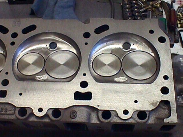 Just a little info: In the $7500 engine
he uses the original block, crank and heads (ported and polished) but
does extensive work on them He does a lot of work on the
oil galleries of the block, oil restrictors to keep the oil in the
crank, replaces all plugs, line bores the crank bearings, all
ARP fasteners, High Volume oil pump, special chrome moly oil pickup
tube, special oil pump baffle, windage tray, special mondello oil
pan with one quart more capacity than the original, special metal and
gasket oil pan gasket. Guaranteed not to leak. all neoprene
gaskets, cross drilled, shot peened and chamfered crank. Polishes
the inside of the stock manifold for better flow, special roller rocker
arms, bronze valve guides, stainless steel valves, forged pistons,
chrome
moly rods, special piston rings hand fitted, special cam with cam
buttom
(ball bearing end) to get perfect ignition timing, and indium coated
bearings
(same as Mercedes Benz). Wow! First class from everything we
discussed.
This engine is for the guy that positively does not want to break down
on the road. He says these engines are bullet proof. He says he has
never
had to replace one yet since he has been building them.
Thomas
Just a little info: In the $7500 engine
he uses the original block, crank and heads (ported and polished) but
does extensive work on them He does a lot of work on the
oil galleries of the block, oil restrictors to keep the oil in the
crank, replaces all plugs, line bores the crank bearings, all
ARP fasteners, High Volume oil pump, special chrome moly oil pickup
tube, special oil pump baffle, windage tray, special mondello oil
pan with one quart more capacity than the original, special metal and
gasket oil pan gasket. Guaranteed not to leak. all neoprene
gaskets, cross drilled, shot peened and chamfered crank. Polishes
the inside of the stock manifold for better flow, special roller rocker
arms, bronze valve guides, stainless steel valves, forged pistons,
chrome
moly rods, special piston rings hand fitted, special cam with cam
buttom
(ball bearing end) to get perfect ignition timing, and indium coated
bearings
(same as Mercedes Benz). Wow! First class from everything we
discussed.
This engine is for the guy that positively does not want to break down
on the road. He says these engines are bullet proof. He says he has
never
had to replace one yet since he has been building them.
Thomas
-------------------
HEADS
Joe Mondello
quote for heads $1399, $1050 to install.-- see web page for all
goodies. gene
HEI Ignition
GMC
Ignition Systems by Duane Simmons
-------------------
Many of us old time GMCers (10 years myself) have found that HEI
Ignition failures are primarily cause by improper spark plug
gaping. The OEM specified gap is 0.080" which
is to great a gap & causes excessive Coil voltage, which can
result in all kind of Ignition damage. The solution, w/o sacrifice
of performance, is gap plugs at 0.060" ( AC R46SZ. Also use only
Delco Ignition Modules & apply an abundance of the Thermal
Conduction Grease on the base of the module during installation.
Recommended spare Ignition parts are as follows:
1) Delco Ignition Module w/thermal grease
2) Ignition Coil (Delco only)
3) Rotor (Delco only)
4) Distributor Cap (Delco only)
5) Spare Ignition wires (2-3 wires)
Also failures occur due to lose of the Coil ground which give
erratic
or
non operation conditions (check for looseness on the Coil mounting
screws
& place both ground wires under one mounting screw).
The GMC Motor Home Distributor is unique in its mechanical &
vacuum
advance curves & therefore a car dist. will
not provide performance w/o
modifications. Try Bob Lamey, 1-909-982-7747 Ontario, CA for an
expert
distributors Upgrade (new GMC Motorhome Distributors are not
available).
I too do not think a failure of the module is justification for
replacement of the distributor (if not done properly, a step in the
wrong
direction).Duane
--------------------
I work at Dana Corp who recently bought Echlin who supplies many NAPA
parts. Several years ago I was the project engineer for ACCEL
distributors made here in Branford Ct.
as part of my job I had occasion to have ignition modules tested with a
variety of different ignition coils. We actually documented the
fact that some TP-45 type modules would not fire some coils at a given
range of RPM (generally the ones
made off shore). The module would literally drop out and not fire
the coil for instance from 1,200 rpm to 1,250 rpm (this can cause
really hard to diagnose performance problems). I am not an electrical
engineer I just know what we recorded. Bottom line, it is best to get
a coil and module for the same application and probably best from a
dealer. I wish I could say that I am sure the NAPA TP-45 modules are
the good ones, I can't, but I bet the $10.99 unit is made off shore.
Alan
-------------------------
rebuild is about $190 and has new shaft, lower bearing and guts, Bob
does them for Cinnabar--
shipping addr is 321 Armsley Sq.
Ontario , CA 91762-1606
gene
----------
Don't throw away or replace that old HEI unit. They're
rebuildable. GM P/N 1894379. This is for a replacement shaft kit
that includes bushings. They're about the only parts of the unit
that can wear out. If you're worried about the advance curve, send the
whole thing to GES engineering here in San Diego. He will
professionally recurve yours, or your replacement, and install an
adjustable vacuum advance kit. Runs around $100 plus parts. He'll
also provide the curve specs. He also rebuilds/recurves older
points type units. Steve Ferguson
--------------
An HEI tester is available at many Auto Parts stores for about
$10. A
must for simple HEI trouble shooting. The
HEI Tester is made by K-D
Tools p/n 2756, "Calibrated Ignition Tester for HEI Systems".
Duane
Hot
To Test a HEI distributor(9/17/06)
Engine Cranks
But Will Not Start
Turn the ignition off, remove the air cleaner, and look down the front
carburetor barrels. Depress the accelerator once or twice while looking
for gasoline squirting into the front barrels.
Gasoline present: go to Step 1
Gasoline not present: Fix missing gasoline problem.
1. With the ignition on, connect a voltmeter (or test light) to the +
post or HEI BAT terminal located on the distributor cap.
+12 volts or Test LIGHT ON: Go to step 3.
No voltage or Test LIGHT OFF: Go to step 2.
2. Check for continuity or voltage drop in the ignition switch and in
the circuit from the switch to HEI BAT terminal. Fix missing +12 volt
problem.
STARTS: Stop—you’ve found the problem.
NO START: Go to step 3.
3. Remove a spark plug wire and insert a HEI spark tester ($2.99 from
Harbor Freight) in line. Crank the engine and observe the light in the
tester.
3a. Alternatively remove a spark plug wire and insert a metallic
extension in the end of the wire. Using insulated pliers, hold the
spark plug wire no more than .25 inch away from the engine block while
cranking the engine. If you use the alternate method be very careful to
hold the wire no more than .25 inch away from the engine. Greater
distances can cause damage to the ignition module.
LIGHT FLASH IN TESTER or SPARK JUMP TO ENGINE BLOCK: The problem is not
the ignition system. Check the fuel system, spark plugs, timing, and
internal engine condition.
No light or NO SPARK: Go to step 4.
4. Remove and inspect the distributor cap for cracks and
carbon-tracking. Visually inspect the distributor mechanism for
moisture, corrosion, or burns. Repair as needed.
STARTS: Stop—you’ve fixed it.
NO START: Go to step 5.
5. Set an ohmmeter to the low scale. Connect the leads across the HEI’s
“BAT” and “TACH” terminals.
ABOVE 1 OHM: Replace coil. If vehicle still doesn’t start, go to step
6.
0-1 OHM: Go to step 6.
6. Connect one ohmmeter lead to the “BAT” terminal and the other lead
to the coil contact in the inside-center of the cap. Switch the first
lead to the “TACH” terminal and recheck.
EITHER TEST READS 6K to 30K: Coil is OK. Go to Step 11.
BOTH TESTS READ INFINITY: Replace the coil. If the engine still won’t
start, go to step 7.
7. Remove the green and white leads from the HEI control module.
Connect the ohmmeter from ground to either lead.
INFINITE reading: Go to step 8.
LESS THAN INFINITY: Replace the pickup coil. If the engine still won’t
start, replace the module.
8. Connect the ohmmeter across the green and white pick up coil leads.
READS 500-1,500 OHMS: Repeat Steps 7 and 8 while moving the vacuum
advance with a screwdriver. If reading is still OK, replace the module.
DOES NOT READ 500-1,500 OHMS: Replace pickup coil. If the engine still
doesn’t start, replace the module.
That is it. You will notice that there is really no diagnosis of the
module. When everything else reads correct the module is replaced by
default. In my case the coil read open. replacing it did not fix the
problem so I had to replace the module also. BOTH items were bad and I
assume the coil took out the module. HTH Ken B.
Upgrading to a HEI Ignition
I think you will find that the GM HEI ignition is very hard to beat for
the Motorhome application. You will
find many GM cars that have an HEI distributor that will fit the 455
& 403 engine. However, the vacuum & mechanical advance
will need to be modified to need our needs. The coach will
run with these car distributors but not very good & damage can
be done to the engine. Best to buy from wrecking yard a GM HEI
distributor & have it upgraded to the correct curves. Look for one
with a GM only Electronic Module, rotor & cap (other after market
brands are not as reliable). Bob Lamey
(909-982-7747.....Ontario, Calif)) is an excellent source for
this upgrade. Bob has a distributor machine that he
verifies/adjust both the vacuum & mechanical advances to our
needs. He only needs the lower part of the distributor (not the
coil/Cap). The change over requires the following:
1 Off set Air intake filter housing
(from HEI car...olds or other)
2 New power wire from Ignition to Dist. Input
3 New Spark Plugs: AC 46RSZ
(0.060") not 0.080"
4 New Spark Plug wires (HEI type with metallic conductor)
5 Set Initial Timing at 8 deg. BTDC
at Idle
Note: Most, if not all, car dist housing has a notch to index
the Cap at 180 deg. from where it should be for the Motorhome
application. File new notch for installing Dist Cap with input
connector
near the Vacuum advance Unit (180 deg from original if required).
Don't want the input connector on port side near the accelerator
linkage.
This Upgrade was one of the best improvements that I did to my coach
(about 9 years ago). Well worth the effort. Duane Simmons
************
Cable harness for the conversion
http://www.madelectrical.com/
Great stuff and a real nice guy! I order an HEI-1 and an ALT-1 from
him.Terry Taylor
---------------
DISTRIBUTOR DIRECTION
Page 6Y-45 and 6Y-59in the X-7525A factory service manual (FSM)
specifies (the distributor turns)
counterclockwise.
Page 6Y-33 in the X-7725 FSM specifies clockwise, which is wrong.
Dick Paterson always points out in his GMCMI convention seminars
that
Olds is
the opposite of other vehicles and the distributor spins
counterclockwise.
Paul Bartz
CHECKING
YOUR DISTRIBUTOR CURVING OR TIMING
I contacted Dick Paterson and he gave me permission to publish the
following info:
Distributor Specifications, Type: HEI - Modified
Application: GMC Motorhome
Engine: 455 Oldsmobile
Final drive: 3.07
Tow: No
Initial setting: 12°
RPM Advance
Centrifugal
800 2°
1000 5°
1250 10°
1500 12°
1750 13°
2000 14°
2250 16°
2500 18° 30° = Total
Vacuum
6" 0°
8" 2°
10" 6°
12" 10° 40° = Intial + Centrifugal
+ Vacuum
As I understand it he has developed a number of different curves for
GMC's with different final drives and whether they tow or not. ROB
---------------------------------------------------
I used the HEI distributor from a 75 Olds Toronado (Cardone #1893)
and changed the vacuum advance to 10 degrees (Delco #1973577). You also
need to change the wires and plugs. Use .060 gap plugs, (not the .080
ones). The larger gap plugs tend to burn holes in the rotor. I use
AC/Delco R44SX plugs but they are getting hard to find. When you
install the distributor you must run a heavy wire (12 ga or better)
directly from the distributor to the ignition switch. This new wire
will bypass the resistance wire that powers the old ignition system.
You will probably have to modify the air cleaner so it will clear
the
larger distributor cap. I used a hammer and it worked find. Or you can
get
one from a junkyard 75 olds Toronado.
It would probably be a good idea to check the timing curves after
installing the new distributor. Here is what I have been told they
should be for the GMC:
Speed No
Vac With Full Vac
-----------------------------
Idle
8
18
2000 18
2500 20
3100 27
In order to check the timing more easily I painted the harmonic
balancer black. Then I painted white lines at 8, 18 and 27 degrees
BTDC. I calculated the positions of these marks by measuring the
circumference of the harmonic balancer (20.5") and dividing by 360.
This gives the length, in inches, of one degree on the surface of the
harmonic balancer. The zero degree mark (TDC) is the reference line
notched into the harmonic balancer. When I cranked the engine so the
zero
degree mark is on the drivers side (looking up from under the engine),
the BTDC marks are toward passenger side in order as follows:
The 8 degree mark is at .46". This is the timing at idle with the
vacuum advance disconnected.
The 18 degree mark is at 1.03". This is the timing with the engine
at
2000 rpm and the vacuum advance disconnected. It is also the timing at
idle
with full vacuum advance.
The 27 degree mark is at 1.54". This is the timing with the engine
at
3100 rpm and the vacuum advance disconnected.
I used white paint to make the lines marking each of these timing
positions on the harmonic balancer.
I disconnected the vacuum advance from the carburetor. Using a
timing
light, I set the timing (at idle) to 8 degrees. If the lines on the
harmonic
balancer are painted correctly the 0 degree mark (the notch in the
harmonic
balancer) will line up with the 8 degree arrow on the engine and the 8
degree
mark (the first painted line on the harmonic balancer) will line up
with
the 0 degree arrow on the engine. Note that the zero degree arrow is
the
first point on the drivers side. The other arrows on the engine are
spaced
4 degrees apart (4, 8 and 12 degrees).
To check the centrifugal advance, I ran the engine up to 2000 rpms
and checked the timing. If the centrifugal advance is working properly
the 18 degree mark on the damper (the second painted line) will
be lined up with the zero degree arrow on the engine. Then I ran the
engine up to 3100 rpms and checked the timing. If the centrifugal
advance
is working properly the 27 degree mark on the damper (the third painted
line) will line up with the zero degree arrow on the engine.
The centrifugal advance on my distributor is pretty close. At 2000
rpms it was right on at 18 degrees. At 3100 rpms it was at 24 degrees.
Thats not quite as advanced as I have been told it should be (27
degrees at 3100 rpm) but I rarely run much above 2500 rpms so I live
with it.
Before checking the operation of the vacuum advance be sure that the
idle timing is set to 8 degrees when the advance hose is disconnected.
Then unhook the hose that goes to the transmission modulator and
connect the vacuum advance hose to the transmission modulator port on
the intake manifold. This will apply full vacuum to the vacuum advance
and should pull in an additional 10 degrees of advance. Use the
timing light to verify that the 18 degree mark painted on the damper
lines
up with the 0 degree arrow on the engine (8 degrees idle plus 10
degrees
vacuum advance).
If you see more than 18 degrees then you have the wrong advance and
should replace it with the correct one - Delco 1973577. If you see less
than 18 degrees then the advance is defective or there is a vacuum leak
or blocked hose.
The curve on this distributor (75 Toro) is pretty close (after I
replaced the vacuum advance). Here is a summary of what I measured:
Speed No Vac
With Full Vac
-----------------------------
Idle
8
18
2000 18
2500 20
3100 24
There are a number of places that will rebuild and properly recurve
the distributor for you if you would like it to be exact. Bob Lamay and
Duane Simmons are two people that where recommended to me.Dave
ADJUSTABLE
VACUUM ADVANCE
The guy who set up my timing over a year ago said not to worry about
the base timing , vacuum advance, and flyweight advance, just set the
total advance to 35 degrees and go from there. How wrong he
was.
 He
did not check the vacuum advance that he
installed with the engine, and come to find out it was adjustable
and was set for 25 degrees of advance. So when that total
advance was set for 35 degrees, minus the 10 degrees of the flyweights,
the base advance was ZERO (0).... As a result I always had this
flat spot in the acceleration when the vacuum dropped at startup , the
timing dropped down to the base advance of Zero and the engine would
act
like it hit a wall until the vacuum would again advance the
timing. The picture shown above shows the setting I found when I
started to
time the engine, and the top arrow shows where I set the final position
yielding 10 degrees of advance. The engine now accelerates
smoothly
through the range and I have overcome a major problem. Thanks to
Dave's great article above on how to check the distributor
curve. My numbers are now:
He
did not check the vacuum advance that he
installed with the engine, and come to find out it was adjustable
and was set for 25 degrees of advance. So when that total
advance was set for 35 degrees, minus the 10 degrees of the flyweights,
the base advance was ZERO (0).... As a result I always had this
flat spot in the acceleration when the vacuum dropped at startup , the
timing dropped down to the base advance of Zero and the engine would
act
like it hit a wall until the vacuum would again advance the
timing. The picture shown above shows the setting I found when I
started to
time the engine, and the top arrow shows where I set the final position
yielding 10 degrees of advance. The engine now accelerates
smoothly
through the range and I have overcome a major problem. Thanks to
Dave's great article above on how to check the distributor
curve. My numbers are now:
idle
7 18
2000 15
total 30
gene
Spark Plugs
Here is a link to JR's spark plug table (11.24.10)
http://www.gmcgreatlakers.org/gmcing/tech_docs_gl/SparkPlugApplicationGuide.pdf
http://tinyurl.com/m87loe2
AC Delco Rapid-fire #7 are a platinum electrode plug that is rated
for 100K mileage. Recommended by Dick Patterson and others.
Run
them as they come out of the box. It is about a 38 to
40 gap from
the factory. Much easier on the HEI. JMHO J.R. Wright
I use Bosch single plat plugs # 4023, put then in a few years
ago and still running good, this is the plug we use here at MGM unless
the customer want another plug. @ 2.99, can't go wrong -
Miguel
The Rochester
Files
Quadrajet stock calibration
OK, here is what I know about the Quadrajet stock calibration.
This information is a composite of a 1991
Caughlin Coach Talk, Doug Roe’s book and the big Rochester parts
book.
Year Carb No. Primary Jet
Primary Rod Secondary
Rod Sec. Rod Hanger
73-74 7043254
70
50D
CJ
V
75-76
Fed 7045254
70
50D
CJ
V
75-76
CA 7045554 68
`
50D
CJ
V
77
403 17057254 67
7043541
CK
V
78 17057559(CA)
17058254 67
7043541
CV
V
The Carburetor Numbers are on the left side, in front of the boss
that runs vertical beside the secondaries. Probably unreadable
with the carb on the vehicle unless you use a magnifying mirror.
There are other subtle differences, such as the power spring (4-8 in
hg) hot unloader (not present) for the 455 and secondary air valve
setting that are unique to the motorhome.
It is important to make sure you have no vacuum
leaks and that you have the correct line connections. Both
problems that I have seen and experienced. The addition
of a vacuum gage and an air/ fuel ratio meter are helpful in keeping
track of your carb performance. An air/fuel
meter is available from Summit, Edlebrock, Westach and probably others,
or you can make one from a three wire O2 sensor and a volt meter.
1 volt = 14.7 A/F. As Arch says, This is
what I know (and maybe a little more). I did give a seminar at a
Western States rally on the subject once. Would appreciate
comments corrections and additions from others. ps I'm a digest
subscriber so it may take a day for responses.
Frank Condos
76 Glenbrook
Monrovia, Ca
ALTERNATOR MOUNTING SPACER (3/29/07)
Most alternators have been changed on the GMC motor homes. It
seems at that time a little spacer under the mounting brackets that go
to the side of the engine block, get lost.
If this spacer is not there, the pulley of the alternator will
not be straight with other pulleys and the belt will wear out fast and
often jump out of the pulley. Here are some pictures that show
the OEM mounting brackets of the 455 and where this spacer is located:
http://www.gmcmhphotos.com/photos/showphoto.php?photo=2013
Here is another way to fix the alignment problem
http://www.gmcmhphotos.com/photos/showphoto.php?photo=3377
Why
does the alternator light stay dimly lit?
As a test, the Alternator light SHOULD BE ON when the key
is on and the engine is stopped. If it is not, replace the bulb.
The Alternator light SHOULD NEVER BE ON, dim or bright,
when the engine is running.
If it is, you should do the following:
Install the APC cable.
This will eliminate erroneous indications that will keep
you from finding the problem.
If the light is still on after installing the APC, the battery
voltage is higher than the alternator voltage. Use your voltmeter
to find if the alternator is not working or something else will
not allow the alternator voltage to reach the battery. The
link above describes several things that could cause this, like a loose
belt.
The alternator light is a very valuable diagnostic tool and an
important part of the charging circuit. It should never be
removed or ignored. Always look to see that it comes on
when you turn on the key and the engine is stopped.
The OEM charging circuit is not faulty. The Nichrome wire
will not get hot with the key on. I have run tests with the
actual nichrome wire that show the wire will not get hot at even 40
volts.
This is ususally a normal condition on pre 77 / 78 models of
GMCs". The easy way to solve this problem is to order the
Alternator Protection Cable (APC). The APC will eliminate the Dim Alternator Light , and damage to the Nichrome Wire. If you look at the pictures in the
following articles, you will see a lot of wire tracing, crimping and
soldering. The APC provides the protection with out all of these
complicated modifications.
ALTERNATOR LIGHT
OPERATION
Not everyone knows the functions of this light. If you have the
original GMC alternator and are using the factory style indicator light
on your dashboard, it is a pretty helpful thing. It helps kick-start
the alternator into working at idle speeds when you first start the
car, and it tells you if the alternator is putting out less voltage
than the battery has in it, indicating a problem.
The light is connected on one side to the field current system
inside
the alternator and to a switched ignition power source on the other
side
(to the fuse panel inside the glove box.) When you turn the key on but
have
not started the car yet, the field acts as a ground and power flows
through
the light and out to ground - lighting the bulb so you know it works.
Once you start the car, the voltage at the field is powered
internally by the output of the alternator. If this value is exactly
the same as the battery voltage, then you have the exact same voltage
on each side of the indicator light and they balance each other
out so the light doesn't light. If all goes well, the light never
comes on, and you drive happily around knowing all is well with your
alternator.
If the output of the alternator should drop due to a slipping/broken
belt or due to certain kinds of electrical faults inside the alternator
itself, there will be less voltage on the field side of the light and
more voltage on the switched ignition side of the light. The result is
that some amount of electricity will flow through the light and into
the field and the light will glow proportional to that voltage
difference. This is how a slipping belt or an overloaded alternator
will cause the light to glow very dimly, while a full-on failure
will cause the light to glow very brightly. Note that if you
disconnect (or forget to connect) the wire at the alternator, the light
will never come on and the alternator may not charge properly.
GMC Tech Bulletin
"Technical Service has received several reports of
the
generator telltale light glowing dimly at all times. This
condition
can exist even though the alternator is operating correctly. It
may be caused by a partially discharged vehicle battery or by the small
voltage drop across the dual diode isolator.
If the above condition is encountered and the owner of the vehicle
expresses concern over it, the following procedure should be followed
to assure that it is not being caused by a malfunctioning
alternator. The owner should then be assured that the
condition is normal and will not cause any trouble in the system.
1. Disconnect the battery ground cable.
2. Connect an ammeter in the circuit at the "BAT" terminal of the
alternator.
3. Reconnect the battery ground cable.
4. Turn on radio, lights high beam, and blower motor high
speed. Connect a carbon pile across
the battery.
{Emery's note: this is to put more load on the battery. Try
turning on a lot of 12 volt appliances in
the GMC if you don't have a carbon pile}.
5. Operate the engine at a moderate speed
as required, and adjust the carbon pile as required to obtain
a maximum current output.
6. If ampere output is within 10% of rated output (80 amps)
alternator is not defective." (Emery Stora)
INSTALL A DIODE TO STOP THE DIM STATUS LIGHT
Cut the brown wire going to the idiot lamp. Insert a 25 cent
Radio Shack diode in the line in any direction. Turn on the
ignition to test. If the light comes on, you're done, just start
the coach and watch the light .go out If the lamp does not come
on with the ignition, reverse the diode (end for end) and you're
done. Get a Radio Shack part number 276-1102 or similar.
(John Dolan)
Plug in an APC cable to stop this problem
DIM ALTERNATOR LIGHT
- FUSE-
There is one other condition that can cause the symptom of a
dimly lit idiot lamp. A GMCer replaced his alternator, and
still had the dim glow problem. He checked a diode that is
supposed to eliminate this on some production models. NO
luck. He then discovered that his 10 AMP dash instrument gauge
fuse was blown. The fuse provides 12 volts to one side of
that lamp and if it is blown it does not have 12 volts there.
When the alternator starts putting out 15 volts there is a differential
15 -
0 and it gets an indication. Replace the fuse (or check wiring
and grounds to make sure you have 11.5 to 12 volts at the lamp and the
glow should cease, except when the alternator is not putting out 15
volts, which is the way it is supposed to work. It was reported
in GMCMN in March 98 page 5. (John Dolan)
----------------
ALTERNATOR RESISTANCE WIRE
FAILURE
The dashboard indicator light circuit also has a resistance wire
with a calibrated resistance in it. This
wire runs in parallel with the indicator light and has about
a 10 ohm resistance. It's purpose is to allow slightly more current
to flow to the alternator field current system at initial start-up to
make sure the alternator begins producing power as soon as the engine
starts. About 1 amp total current is flowing to the field current
between the
light and the resistance wire, with the resistance wire supplying about
3/4 of an amp. This extra resistance wire does not affect the
functionality of the indicator light in any way.
This resistance wire has been known to overheat (perhaps due to
bad diodes or a bad voltage regulator in the alternator).
When it overheats it melts the covering of the wires in the wiring
bundle that runs under the dash padding by the windshield on the
passenger side. This will short out all kinds of things and
could even start a fire.
Someone has proposed replacing this resistance wire with a
regular
wire in series with a 10 ohm resistor, keeping the resistor away from
other
parts so that if it overheats it will not melt anything or cause a
fire.
Emery
************
The Ni-Chrome wire is an excellent high power resistor and GM made a
good choice. The problem is, when something
goes wrong with the isolator, or alternator, a higher voltage is
placed across the wire and it gets hot and burns up the wiring bundle
and causes a big problem. These pictures show how much damage is
done by this condition.
http://www.gmcmhphotos.com/gallery/showalbum.php?aid=139&&uuid=lowglide
> in the GMC ckt, the only way to get high voltage is for the
regulator to fail in a specific failure mode, this delivers 100 volts ,
blows up batteries, and burns wires....etc.
see this example
----------------------
I was not so lucky and not only did the isolator burn out,
but I also had the alternator burn up just prior to the battery
exploding. Fortunately no one was hurt and this all occurred in a shop
where the
AC was being re-chaged and being tested. Yes, the AC fan was on
and that also burned up. The shop mechanic said he measured the
alternator voltage just prior to the explosion at 90 volts and
couldn't shut it down fast enough. We are not sure what caused
the chain reaction but it must have been a failed voltage regulator and
probably a bad battery ... but definitely a failed isolator. Yes,
I
now have a combiner and after a $1,200 bill, everything is
working nicely.Dave Bockman 11/07
-----------------------
IF
THE WIRE BUNDLE HAS ALREADY BEEN DAMAGED
REPLACE THE WIRE WITH A RESISTOR
The only time the wire should draw power is when the
alternator is stopped and the key is on. Then the wire
could
dissipate (12.5 * 12.5) / 10 or 15.6 watts. Good design
says if you replace this with a discrete resistor it should be
2 * 12.5 or a 25 watt resistor. this is a large resistor and
hard to place, so the Ni-Chrome wire is a good choice.
Also,
the diode should be placed between the alternator and the resistor and
the
alternator light like it is in the APC.
http://www.gmcmhphotos.com/photos/showgallery.php?cat=3254
Some shops have replaced the Nichrome wire with a 100 ohm
resistor. This is a modification of the GM design and
sometimes creates a sluggish startup of the alternator.
See these examples:
>
> I tried an experiment a few years back I disconnected the nichrome
wire circuit to the alternator and ran that way for sevral
months. My alternator always started. When Lawrence tried
the same thing his would never start. So we definitely need some
kind of start circuit. >
---------------------------
100 ohms provides .12 amps will work though I did see one
coach modified that had to be reved up to about 2000 RPM to get
it to start charging. kenB>
---------------------------
There are other famous examples of the 100 ohm resistor problem
( emails from 22/21/07)
-----------------------
>2/21/07
removed the hot wire and installed a stranded wire and a
resistor. If my coach has been sitting for a long time it will show
almost no voltage for 2 or 3 min. Then all of a sudden it come up. Take
Care
Arch
------------------------
The reason your alternator is slow to come up is that resistor
I'll lay dollars to donuts it's 100 Ohms, ten times the OEM 10
Ohms. Reduce it's value back closer to the 10 Ohms and your
alternator will receive proper initial excitation of its field. Ken
H.>
-----------------------
********* see pictures to view the
permanent wiring changes.
Pre 77/78 models http://www.gmcmhphotos.com/photos/showgallery.php?cat=3247
77/78 models http://www.gmcmhphotos.com/photos/showgallery.php?cat=3254
damage done
http://www.gmcmhphotos.com/photos/showphoto.php?photo=1546&cat=3139
STEP
BY STEP PROCEDURE TO REPLACE NICHROME WIRE
1. Disconnect the shore power to kill the converter.
2. Disconnect all batteries.
3. Remove the glove box to gain access to
the fuse panel.
4. Remove the screws holding the fuse panel to the fire wall and
unplug the connector on the outside of the firewall from the fuse
panel.
5. Locate the brown with white stripe wire (if you roll that wire
between inside) and extract the connector from the back of the fuse
panel. On the outside of the firewall, this lead connects to the
brown 16 gage wire leading to terminal 1 on the alternator. Its
purpose is to provide initial excitation current for the alternator
field (since there's very little residual magnetism in the rotating
field of an alternator, a little bit of "excitation current" is needed
to get things started; as soon as the stator starts producing current,
it takes over and this lead is superfluous).
6. Cut the connector off and solder it to
a 12" length of 14-16 gage wire, then re-insert the connector
into the fuse block.
7. Tape the cut end of the resistance wire for short protection
until you locate and disconnect the other end near the ignition switch.
8. Locate the 12 gage brown wire which leads to the accessory
buss bar in the fuse panel and attach to it another 12" length of 14-16
gage wire. I stripped 1/2" of insulation from the 12 g. brown
wire and soldered and taped the 12" wire there.
9. Mount a 10 ohm, 20 watt ceramic resistor (Radio Shack should
have one, preferably with an insulated mounting bracket) in a
convenient location near the fuse panel. Attach one of the two
added 12" wires (cut to fit) to each
end of the resistor. Be sure no conductor
can contact any exposed 12 VDC terminal.
10. Put everything back together.
11. Reconnect the batteries and "smoke check" everything.
12. Crank the engine and check alternator
output (battery terminal voltage) for 13.5 VDC+.
13. The next time you pull the instrument
cowling, refer again to Lionel's picture and try to find the splice
where the resistance wire is connected. If you find it, cut it off
close and tape the bare ends. While there should be no current
through the wire after you've cut the other end, it is conceivable
that it could still be shorted to ground somewhere and cause the
infamous
"smoking wiring harness".HTH Ken Henderson
***********
Dual Belt Alternator Pulley
I have always had problems with the alternator belts on my 80 Amp
alternators. When I replaced the last 80Amp alternator with a 100Amp
unit I decided to replace the single belt pulley (that comes with the
100 Amp alternator) with a dual belt pulley. The pulley I found is a
bolt-on replacement made of machined steel, 2 5/8" dia., part number
1101, manufactured by BBB Industries. It costs $7.88
and can be ordered from Kevin at Hedahls Auto Parts in Bismark, ND.
(800-472-2112). The 2 5/8" diameter pulley is small enough so that
the 100 Amp alternator will generate 80+ amps at engine idle.
When I replaced the alternator I also replaced my belts with two
Gates XL-7570 (3/8" x 57-5/8") for the alternator & PS pump and one
Gates XL-7619 (3/8" x 62-1/2") belt for the A/C compressor.
I only have about 3K miles on the 100 amp alternator with a dual
pulley but so far so good. Even with the alternator putting out a full
100Amps my belts stay put and make no noise.
I would suggest replacing all of your belts with new ones. My
experience is that when you mix old and new belts, the old and new
belts will be slightly different sizes. That causes the older belts to
ride deeper in the shiv and the new belts to ride higher on the shiv.
Thus the new and old belts fight each other. Since two of my belts
share all pulleys, and three belts share pulleys at both the crank and
the water pump, I replaced all of my belts with new ones. Dave
Timing Chain Replacement
100,000 mile
replacement (Heinz)
In my experiance the single non roller timeing chain stretches at
70-90K miles. That is not a maybe, it is a for certain.
When that happens, your performance drops off as the loose chain
allows the timing to go all over the park. This condition happens
slowly (kinda like how my eyesight has gone bad). Then you
go out and get glasses and then wonder how you didn't no0tice how blind
you were! The timing chain & gears go bad gracefully until
that fateful day when it jumps a tooth under load and then the fun
begins.
I would say thay the single best thing you can do for your
approaching 100K motor is to replace the old (mearly mortal) chain and
gear set up with a double roller, true rollerchain/ gear set.
They will never go bad, you can keep them for the next rebuild.
They eill be quiet, reliable and give you the assurance that the
crank and cam will be tied to each other no matter what. Of
course
while you are in there, I would suggest replacing the water pump, fuel
pump, front seal and fan clutch. All of these components will
be off and on the floor while you dig to reach the timing chain.
The labor will be free to replace them and then you will have the added
relief of knowing they are hunky dory too.Jim
Installing timing chain
without removing radiator and fan shroud. (11/25/06)
While replacing the timing chain I found that the transmission
cooler line fittings were rusty and stuck in the radiator cooler.
They were still frozen after using Kroil over several days. I was
afraid of damaging the radiator if I forced the issue too much.
Since I did not want to have to fix something that was not broken, I
came up the following work around. It's a little tight and would
probably be easier if the radiator, fan shroud, and transmission
cooler lines were removed. I am sure others have done some
variation of this before but, I thought I would share my
technique. I'm working on a '78 403cid with a full coverage fan
shroud.
Installing timing chain without removing radiator and fan
shroud.
1. Before removing old timing chain, rotate the engine so
that the timing mark on the crank gear is down (6:00) and the mark on
the cam gear is at 9:00.
2. Lay out the new gears with the new chain so that
the timing marks are lined up (crank mark 12:00, cam mark 6:00).
3. Carefully rotate the gears on the chain so that
the crank gear is at 6:00 and the cam gear is at 9:00(½ turn
on the crank gear and ¼ turn on the cam gear).
4. Take liquid paper and mark the chain link that
corresponds to the timing marks on the crank & cam gears (I also
colored the timing marks on the gears so that they were easy to
recognize at an angle and low light.
5. As an extra measure use tie-straps and secured the
chain to the cam gear and another to the crank gear (Since I was using
a double roller set the crank gear has extra key slots to run the
tie-strap through.
6. Install the chain and gears. The tie straps keep the
chain on the gears and the marks provide secondary evidence that the
gears are lined up. Before pushing the crank gear home, cut and
remove the tie-strap so that it does not get pinched behind the gear.
--
How to Replace the Chain (Removing shroud)
I had a chain I Had picked up from Joe Mondello [Phone (805) 237-8808,"
& it was a Cloyes Timing chain] last year and now was the time to
install. While the Manual is usually good in describing how to do
things in this case it is poor and not even accurate ,as it says you
have to remove the oil pan and you don't have to, in fact you can't
remove the pan!
Every thing can be done from the front-at least in my case as I have
already removed the large round metal and rubber spacer between the
radiator and the fan (not the fiberglass part attached to the rad.) see
Ken Thomas' excellent idea in GMC Motorhome Marketplace April,1997, re
getting rid of a lot of the clutter in front of the motor and making
this area much easier to access and work in. Having done this ,I've
found this to be one of the very worth while changes to
make to the motor area. This gave enough room to work and get your head
up in there to be sure that you get the timing marks in the right
place. It is a bit tricky as the new chain goes in with absolutely no
slack. I learned from the experience of pressing the chain on and found
that I was one cog off, so had to pull it off again.Take your time and
eye ball it to be sure you get the marks lined up correctly.
In my case I got some antifreeze into the oil pan so be very careful
to drain it out and keep any bits of dirt etc. from getting into the
pan when the area is opened at the front. I ended up in draining the
oil pan as well as having to do some mopping in there with rags but
likely if one got some rags in at the start it would be better and save
the extra work and mess. Also when draining antifreeze have back end of
coach high and after draining by lowering back end you might save some
of the antifreeze from draing foreword from the block.
As I recall I had to undo the front motor mount so you will need to
find a way to support the weight of the motor. I used some 2x4's on
each side of the motor on the vertical.
I was amazed at how it quieted down the motor,now having a tight
chain.
I also find that my Ping Alert is much more accurate as it is not
picking up extraneous other noises in the motor.
Good luck.
Claude in Victoria BC.
_____________________________________________
[INDEX] | [SUGGESTIONS]
