 Tray extends to the end of the
battery
Tray extends to the end of the
battery 
want to know how this works ?? look here
http://www.gmcmhphotos.com
Do you know why the rear markers doe not blink ?
http://www.gmcmhphotos.com/photos/showphoto.php?photo=5805
TURN SIGNAL SWITCH
AutoZone part number SW326 or SW327.
This is a very common turn signal switch used by GM on vehicles of
that era. It is not GMC motorhome specific.
These are made by Wells. The difference in the two numbers is
that one also included a set of contacts for cornering lights.
The cornering lights are actually a separate connector that plugs into
the same switch that
you do not have to use. Wells is actually the manufacturer of the
switch for
Delco (GM) . My Wells switch came with the Delco inscription on
the
plastic molding.
The problem you will run into is there was two different plugs used on the connector depending on the year the coach was made. One is slightly longer and will not plug in. These part numbers from Autozone come with an adapter to fit both cable connector styles. MAKE SURE THERE IS AN ADAPTER IN THE BOX WHEN YOU BUY IT. You may need it.
If yours is the opposite plug type and you do not want to use the adapter, you can remove the pins from the old plastic plug and insert the new cable pins into it. The pins are the same only the plastic housing is different.
Ken Burton - N9CV
SHORE POWER
The GMC Shore Power Cable was built by the factory with #6 AWG wire,
which makes it very stiff due to the type of insulation used & the
number of strands within the copper wire. #6 AWG wire is rated at
50 amps for a closed environment...even higher for outside application
w/o housing around it. The Shore Power Source Circuit Breaker
(CB) is what counts in terms of safety....50 amp circuit breakers at
the park's breaker box is just fine for the #6 wire. Any smaller
cable wire will require a smaller shore power circuit breaker rating,
such as 30 amps for a #10 AWG cable. The
OEM (most coaches) shore power source is normally a 4 wire service with
two
hot wires at 240 vac (lead to lead), a center tap neutral wire (return
wire
for either leg of the 240 v ac...120 vac use). Since our coach
does
not use 240 v ac for any application, we theoretically have 50 amps for
each
Hot leg (100 amps of 120 v ac power). So if the source is rated
for
240 v ac at 50 amps, we do have 100 amps at 120 v ac available.
The
coach main CB box provides a main switch/CB of 40 amps, which limits
the coach to two 40 amp source (80 amps total). If a over load
occurs within the coach, the 40 amp main CB will trip before the shore
power CB trips.
An inductor is a coil of wire that will restrict/impede the flow of
AC current & will heat up the same as an equivalent resistor value
(as in an electric heater). Operating the coach at maximum load
(80 amps) can
be a bit sporty with the shore power cable coiled up nicely in its
electrical box (creates an inductor). It has been reported at an
FMCA rally, technical seminar, that fires have occurred due to the
coiling of the shore power cable into a small electrical storage
area. When I plug into shore power, I always pull all the wire
out of the storage area & lay it on the ground in a straight line
to prevent the coil effect. This will also minimize the
voltage drop (maximize the ac voltage available) of the shore power
cable while running under loads.
Type "SO" wire/cable is a much better choice than the OEM
for the shore power cable, since it has a neoprene rubber jacket &
has very fine wire strands. Type "SO" is rated at a much
broader range of temperature operation w/o becoming stiff &
brittle.Duane Simmons
1) W/O any AC power
at the coach, remove the cover from the AC Circuit Breaker Box &
attach
an ohm meter to the Neutral Buss (white wire)
& the Chassis Ground Buss (Green or Bare wire).
2) These two
electrical
points should be isolated...should have high resistance.
3) If not, then the
two points are connected together somewhere in the coach & must be
isolated from each other.
4) W/Ohm meter
attached, start removing one small white wire (not the incoming power
cable wire) until the two points become isolated from each other
(Low resistance). The last small wire removed is the circuit that
contains the connection
between the Neutral Buss & The Chassis Ground. This
connection
must be removed to enable a GFI Shore Power source to function w/o
tripping.
5) Now reattach the
small white wires that were removed except for the one that was removed
to isolate the two points. With all small white wires attached,
except the last one, there should be high resistance between these two
points.
6) Trace the last wire
(disconnected) circuit to determine where the Chassis & Neutral
wire
are connected.
That's all there is to it........Hope this helps...BTDT Duane Simmons
This is a simple description of the operation of a GFI
device.
GFI -Ground Fault
Interuptor- Operation and Testing
HEADLIGHT
SWITCH(4/4/06)
According to my files the correct headlight switch is #HL6554 or
Delco D1558
or Standard BlueStreak# DS155.
The Borg-Warner S427 and Napa# HL6613 are correct for the 74-76
Toronados. DENNY
You can add the NAPA HL6613 to the list of headlight switches
that WILL work
In our GMCs. The nice thing about it is that it was in stock at
our little NAPA - Arch
here is the picture of the switch
http://www.gmcmhphotos.com/photos/showphoto.php?photo=16289&ppuser=9
http://www.gmcmhphotos.com/photos/showphoto.php?photo=16284&ppuser=9
You can ad WELLS SW144 to the list of headlight switches too. I just
got one at Auto Zone for $10.98. They were able to cross reference the
Borg-Warner number. It looks just like the one Arch got at Napa. It is
even missing the same blade. richard
How to link by J Harper (1.11.2012)
http://www.gmcmhphotos.com/photos/showgallery.php?cat=4792
NON-WORKING DASH LIGHTS might be related to the installation of a new radio.
For anyone putting in a new radio, bear in mind that the GMC original radios used a separate wire for the panel light in the radio so that it could be dimmed when one wanted to dim the dash lights. Not all newer radios use this feature.
There is a grey wire that connected to the original radio for the panel light. If one were to test this wire with the dash lights off, it would appear to be a ground wire as it would ground through several instrument panel light filaments to ground. If this wire is used to connect to the radio ground wire it turns out that the radio will work just fine as the resistance of several bulb filaments in parallel will not put much resistance in the circuit.
The problem is that when the lights are turned on, the current
through the dash light fuse is immediately shorted to ground through
the radio and will burn out and the dash lights will not work. If
anyone is planning to install a new radio you may want to keep this in
mind.
The little tags over the Fuel Tank selector, Battery Boost Switch,
Light Switch, etc, were originaly lighted with a fiber optic
assembly. This never worked on my GMC. I did not want to
remove the dash board to replace this assembly with lights, so I did
the follong procedure using the LED solution
http://www.gmcmhphotos.com/photos/showgallery.php?cat=4029
This upgrade can be done from the front of the dash board and the
cost is about $ 5. gene
Len Novak used an sells an EL solution
http://www.gmcmhphotos.com/photos/showgallery.php?cat=4375&ppuser=439
http://www.bdub.net/novak/
Think about the water analogy for a moment. If you have a
water
tank and its always empty the next morning, THAT WATER HAD TO HAVE GONE
SOMEWHERE! If you look at each tube that goes somewhere from the
water tank, and see if water is flowing thru it, you WILL find where
that
water is going!
Batteries are pretty much like that. Either the electricity is leaking out thru a wire somewhere, or else the battery is old and sick and is leaking internally, in which case its a goner. Get a new battery.
The way you measure electricity flow is the ammeter. It is one of the functions available in those little handheld "Multimeters" you can get at Radio shack for $25.
Here's what you do: Disconnect the wire in question and connect the ammeter across the gap you have just created. (Connect the ammeter's red wire to the side that is closest to the battery.) Caution: Make sure that everything is turned off when you do the test. If there is, say, 15 Amps flowing somewhere, you could blow out the meter.If it reads zero, there's no leak here. If it reads something really small, like 10 milliamps (0.01 amp), that's not the problem either.
So to start, disconnect the big red wire from the battery and connect the ammeter between the battery and the big red wire. Any current flowing? If so, you are on the trail of your leak. Reconnect the big red wire and go to its other end and check each of the wires that go off somewhere from it. Another place to do this is at a fuse panel. One by one, remove a fuse and connect the ammeter in its place. If current is flowing, you are getting closer to your leak. Keep stalking the leak.
If no current was flowing, its probably the
battery. Leave it disconnected over night. If its' dead in
the morning, get a
new battery. If its not dead, then the leaker only comes on
occasionally. Keep
looking for it.
When I bought my GMC, all 3 batteries would run down over
night. The RV shop guys couldn't figure it out. I checked
everything with the ammeter and found that:
1. One of the 2 house batteries was very sick.
2. It was draining the other one down.
(They were connected in
parallel.)
3. The dashboard rocker switch, which had lost
its labels, was in
the position that connected the house batteries to the engine battery,
thereby running it down too.
Got a new battery and the problem was solved.
BTW, did you ever wonder why the positive direction of flow of
electricity is considered to be from the positive terminal to the
negative terminal,
when, in fact, the electrons really flow from the negative terminal to
the
positive terminal? It was Benjamin Franklin who decided that and it has
stuck
ever since.
The same Benjamin Franklin who wanted to name the turkey our national
bird.
Dick Elsley
I finally got to work on the GMC tonight, in the dark. I put in a fresh fully charged 12V engine battery with only the POS cable connected. Then I rigged a test light using a small dash light bulb and test leads between the NEG Cable and the NEG post on the battery. The light showed through the windshield. I pulled every fuse in the glove box fuse block until the light went out on the last fuse. It was the Dash Radio/8Track Player circuit. This radio does not light up and seemed to be dead. I replaced the fuse and was able to turn the test light on or off with the radio on/off switch. Tomorrow, in the daylight, I'll reconnect the engine battery and monitor it for a while. Amazing! Jack
Windshield Wipers rebuild
Bill Telgen, Dixielanders member, rebuilds windshield wiper
motors. If I
recall correctly from Bean Station, he gets $150 exchange. Older
Thunderbirds & some Lincolns used the same basic motors. He
can convert
those for GMC. He may even be in the market for cores.
He doesn't have a published email address but is in the GMCMI roster.
Speaking of which, the GMCMI roster and the petrified Parts
Interchange
Index (with my numerous notes) is worth the cost of my membership --
.Ken Henderson
Battery Tray - Front mount--non-sliding
A new battery tray is available from Angelo Ragusa, Santa Ana, CA
949-261-5898. The Tray fits the OEM battery bracket & allows
installation of one Engine Battery & two Golf Cart batteries (6
volt ,
T105 size) for the house battery. Made of aluminum & cost
$68. This
arrangement is very popular with the 23 ft Birchaven (all batteries up
front).Duane Simmons
They also make a sliding tray that does not work. Buy the TZE+
Steverson Sliding Battery Tray
The sliders have plastic wheels
Made of steel so do corrode
Lifetime is about 5 years
Tray extends to the end of the
battery
The tray fits in the compartment beautifully and I did take out the aluminum cover as it does help to have that there anyway. The tray holds the two golf cart batteries and there is still room on top. The tray is metal and has sides and bolts on the end to fasten down the batteries. The tray is on roller bearings and they are strong enough to let the entire tray come out and still be able to see the back water fill opening. I tried the ragusa but, as you said, it doesn't come out all the way. The Stevensen comes from trailer trays they sell. It comes out all the way, and then when it is in it can be locked in place. The lock is a slide pin like you see many other applications.
The slide tray width is 9 3/4 inches wide.
Looks like they cut off a little of the flange arround the GMC
opening for the slider. This allows the slider to get closer to
the rear of the coach.
The height of the tray is
3 1/4 inches
The batteries sit down into the tray almost to the bottom or about 1/2
inch up from the floor. There is a lot of top room for the
batteries shown. The whole slide tray sits on a 1/2 inch of
plywood in the bottom of the opening. There are 3/4 inch
boards arround the sides of the batteries at
the bottom for spacers.
---------------------
From what you say that the coach had be sitting 3or 4 years and these are the same batteries that have also set the same time length it would be better to replace them.
For the chassis battery (engine starting) get the biggest, highest CCA (cold charging amps) you can find. Walmart sells a 1000 CCA battery for about $60. This size battery will provide a reserve starting power than the lessor rated sizes.
As for coach batteries it depends on the layout of your electrical
system. If you have the single big battery in the rear with a small one
for the
onan most GMC'ers have change to 2 6volt golf cart batteries in series
and
eliminated the starting battery for the onan, instead using the coach
batteries
for starting. You should get 6 volt golf cart batteries of at
least
220 to 225 aH size. Interstate and Trojan are the most popular
brands, but I am sure that you may find batteries of the same rating
and Costco or other discount suppliers. The choice is yours.J.R. Wright
----------------
Not a Myth! The book "Managing 12 Volts, How to upgrade, operate,
and troubleshoot 12 volt electrical system has a very good explanation
on
pages 50 thru 52 why connecting batteries in parallel has many
problems.
I will paraphrase the section, "An easy way to increase capacity is
to parallel a new 12 volt battery with an existing battery or two new
12 volt batteries to increase capacity. The main problem with
paralleling batteries is if the batteries are not exactly equal in
construction or
degree of sulfation on the plates the battery internal resistance's are
different. The battery with a lower internal resistance supplies
a
greater amount of current to a load than the battery with a higher
resistance.
Also if one battery has a higher voltage that the other a small
circulation
current develops between the two parallel batteries. The higher
voltage
battery is recharging the battery with a lower state of charge.
The
2 batteries react just like two water tanks, one being
full and the other being half empty. water seeks it own level so the
full tank flows into the half empty tank until each has an equal
amount. The same with the batteries, you now have two partially charged
batteries. If you put
a new battery with a dying battery you will kill
both of the batteries. It is recommended that when a high
capacity
battery bank is needed 2 6 volt high capacity batteries in series work
better
and have a much longer life than a parallel battery layout. J.R.
Wright
------------------------
THE DIFFERENCE IN BATTERIES
http://www.amplepower.com/primer/which/index.html
Golf car batteries are an excellent choice as they are designed to
be
drawn down rather far then recharged. Starting batteries are designed
for
lower internal resistance so they can provide high power density
for
short periods of time. On my coach I put an auxiliary battery
holder
on the driver's side and have the starting battery there and have
plenty
of room for a pair of golf cart batteries on the other side.
Jerry
-----------------
For house batteries use two six volt golf cart batteries in series. If you use two twelve volts in parallel they will try to charge each other and result in fewer available coulombs than if you go the six volt route.
I run 2 golf car batteries (Trojan 104s) in the rear battery compartment of our Palm Beach. The larger capacity batteries are too tall to fit into the compartment without some modifications. I've gone to the TrueCharge 40+ battery charger available from West Marine under their brand, or from Statpower (the manufacturer) in British Columbia.
Using this setup I can go 2 days during the summer before I need to recharge. During the 2 days, our load is primarily determined by the fridge. We still have the original fridge, so I don't have the option of propane. We used 2 lights (originals) for 2-3 hours per day, ran the radio a bit (1-2 hours per day) and still had enough juice left in the batteries to start the genset. Once I had to start the coach first in order to start the genset - after we'de run 3 days without any recharge.
Things to do that will extend boondocking time:
1. get a propane fridge! Probably the biggest improvement.
2. when boondocking use the "middle 50%" of the battery bank capacity. This means discharging until about 30% capacity is left and then recharging to 80% using the genset. You can recharge the 50% in about 2 hours depending on the charger. Shore powered recharge to 100%.
2. consider halogen lights or florescents (best) for better efficiency
3. look at your DC systems that include dimmers or speed controls. If they use load resistors for controlling speed consider replacing with an electronic PWM controller, it's more energy efficient but more expensive.
4. switch to a charger like the TrueCharge that can recharge to an
80% level in a few hours ( I try to use only about the middle 50% of
the battery bank capacity since it recharges quickest)
You can also get a good feel for your own power consumption by
installing an ammeter on the house battery and watching your
load. Alternatively, run a few specific tests like I did to determine
how long your battery banks last under what you think will be
your typical usage. Lastly, make certain
that your house and coach batteries are isolated - that way when you
make
a mistake, you can still get everything started. Or, if you're
really
paranoid like me, carry a portapak booster battery just to make
sure.
Henry
I have a sad tale to tell. The coach caught fire when the cable from the house bat that runs down the driverside of the rig to the isolator rubbed through the insulation------shorted out and caught fire. The fire burned up the cockpit drivers seat side wall and end cap in cockpit. There is a service bulletin on this problem. You are supposed to put the cable in the plastic conduit. The cable where it crosses over the frame in the front was dry and hard. When you pulled on it cracked and poped. Then I went inside. Just behind the drivers seat where the cable begins to travel down the sidewall there it was. The conduit and wire had worn through. There was green crud where the copper had been exposed. No signs of arcing or anything just bare wire. Then I found a place where mice had eaten through everything. I replaced it with 2/0 and conduit. After it leaves the driverside of the engine compartment it goes down that side of the cockpit wall T BTW it takes 25 feet of wire to replace the entire cable. NAPA has it in boxes with 25 feet in it. MEASURE IT before you leave the store. It is not a fun job running the cable and conduit down the wall I started up front threaded it through the wall and I was about 18 inches short.
The number of the bulletin is 77-TM-4. It is listed under
12-chassis-
Electrical-2. It was issued June 1977..Arch
It appears that the house battery cable on some coaches from 1974 to
1977 serial 1456 had an abrasion problem. This is also noted in
GMC Motorhomes International Newsletter Issue 24 where the "fix"
proceedure is described. My coach falls in thes era ---
going to check it out PDQ. Gary
Fuse Blows in Clearance
Light
Circuit, License Plate light does not work
Battery Isolator Testing
The Engine Alternator charges the house battery thur the 2
Battery
Isolators while driving. A simple test to see if your
battery
is being charged is to attach a DC Volt meter across the battery
in
question & read the voltage. Now plug in to shore power
&
the Battery Voltage should increase more than 3/4 volts.
Remove
shore power & start up Engine, the battery voltage again
should
increase more than 3/4 volts. Stop Engine & plug in for
Onan
Power (operate Onan), the battery voltage again should be
increase
more than 3/4 volts.
Note: The Engine is isolated from the House battery & should not be charged from the Shore Power Or Onan Power. Also if you want to see if your Onan battery is functional, remove Onan Power to Coach & see if you have 3/4 volts increase with Onan operating. Duane
Buy one simulated sinewave inverter of the 1000 watt size, for the heavy loads.
If needed, buy a low power pure-sinewave inverter for the
noise
sensitive stereo. Laptop (LT) computers charge an internal
battery
and do not require a clean power. I have used my Desk top (DT)
computer
on a simulated sinewave inverter with no problems. However
if
you are concerned about the power to your computer it is a relatively
small
load that could run on your stereo inverter. .
| DEVICE | WATTS | SIM SINE | SINE |
| BLENDER | 300 | X | |
| CAN OPENER | 100 | X | |
| COFFEY MAKER | 1000 | X | |
| DRILL 3/8 " | 500 | X | |
| FRYING PAN | 1000 | X | |
| FOOD MIXER | 300 | X | |
| HAIR DRYER | 1000 | X | |
| IRON | 1000 | X | |
| MICROWAVE | 1000 | X | |
| READING LAMP | 100 | X | |
| TELEVISION | 700 | X | |
| TOASTER | 1500 | X | |
| VACUUM CLEAN | 1000 | X | |
| VCR | 50 | X | |
| STEREO | 500 | X | |
| COMPUTER (LT) | 100 | X | |
| COMPUTER (DT) | 300 | X | |
| SOLDERING IRON | 1000 | X | |
| IMPACT WRENCH | 1000 | X | |
From this list you can see you do not need to buy a $1500 sinewave inverter to run your $100 microwave. Most of the AC loads in the Motor Home do not require pure sinewave power. The simulated sinewave inverters are more than adequate for most of the loads and if they create RFI (radio frequency interference) noise turn the invertors off when not in use. The 1000 watt inverters are typically on sale for $300 to $500.
Gene
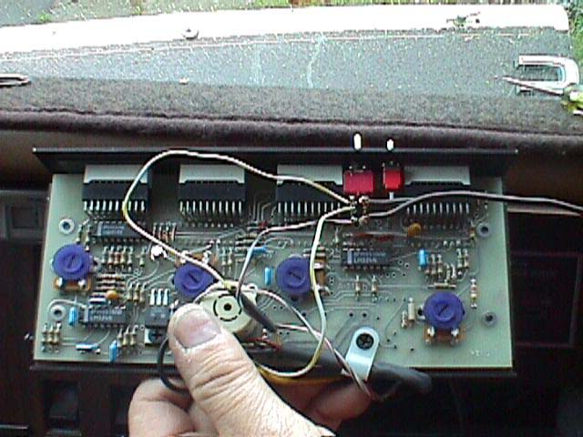
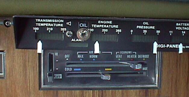
When I first bought my GMC I thought to my self, "that DIGI-PANEL is the first thing I am going to remove". Now it is the last item I would remove. Mine is mounted under the top lip of the dashboard over the instrument cluster on the right side. This set of digital indicators monitors:
Transmission Temp
Engine Temp
Oil Pressure
Battery Voltage.
I love my OEM analog gauges but it is very comforting to compare the analog reading with digital resolution. There are different colors for WARNING, and DANGER levels. The audio alarm will sound when the DANGER levels are reached. This warning broke me out of my revery to warn me that my alternator had failed and my battery was down to the critical level. It also became clear that I had very low oil pressure because when I was stopped with the engine running the alarm sound.

The photo shows the four pointers made from white tape that I added
to my DIGI-PANEL. I stole this idea from Claude Brousson.
These
pointers allow me to take a quick glance at the indicators and
immediately
see that I am running at the nominal levels. The Audio alarm will
tell
me I have a problem when I am not looking.
-----------------------------
For those of you odering the digi-panel, suggest you buy an additional
sensor for the transmission. I did for bout $8 and I added a
small switch which
I use to change from one cooling line to the other. That way I
can
measure the cool, and hot lines from the trasmission by flicking a
switch.
I used one of the miniature switches and used the blank hole next to
the
on off switch to make the connection. Works great.al
REPAIR
Carefully remove the shrink fit tubing and check / resolder the
connections to the sensor. I have had to repair two of these
connections. gene
This picture shows the coolest mounting I have seen for the
DIGI-PANEL. Jim Bounds at the WWW.GMC COOP.COM
has mounted the digital indicator over the new radio. Go visit
him,
I am sure he would be glad to do it for you also.
----------------------------------
1. Send an E-mail to
digidevices@highstream.net
2. Call Art Woodell at 559-665-1546 and his cell phone is 559-223-0181
3. Write
Art Woodall
Degi-Devices
23815 Avenue 26, Chowchilla, CA 93610
or P.O. Box 178, Madera, CA 93639.
http://www.digi-panel.com/digidevicesweb/index.html
MODEL J FOR GMC MOTORHOMES -they are made specifically for GMC's - plus the NEW install instructions will be included --EACH one of you will need to make your own arrangements for payments -- Art takes Credit Cards or you can mail the check to him Pete
The Model J has been modified to use the same Oil Pressure sender that the dash Gauge is using. This makes it easy to connect the DigiPanel. The Dash gauge supplies the voltage to for the DigiPanel to read the oil pressure. The dash gauge must be connected for the DigiPanel to read the oil pressure.
The original DigiPanel supplied a constant current source for the
oil
pressure sender and must use a separate sender. The sender to use
is
:
NAPA
OP6636.
These are also available from General Automotive and DigiPanel.
This is the sender to use for the Dash gauge in the GMC. gene
----------------
Talking to Art I found that he also has another option. He has
the panel set
up for an oil temperature sensor as well. He uses a switch to
read either
transmission temp or oil temp. It comes with an extra probe that
can be used
for either oil temp or for a second location on the transmission.
It is
$27.50 more.Emery Stora
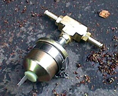
 This
is Mr.C
under the coach installing the pressures sender. We elected to
put the Pressure sender at the fuel
pumps which are located just after the tank selector valve. The
sender
is the same one (part number shown above) used for the Oil
pressure on the GMC coach and was purchased from Digi-Panel for $13.00
.
This
is Mr.C
under the coach installing the pressures sender. We elected to
put the Pressure sender at the fuel
pumps which are located just after the tank selector valve. The
sender
is the same one (part number shown above) used for the Oil
pressure on the GMC coach and was purchased from Digi-Panel for $13.00
.
 The
Sender
supplies a variable resistance of about one ohm per pound. The
Howell system operates at a fuel pressure between 16 and 24
pounds. This will give about a one half scale reading on
the Digi-Panel. This measurement does not require extreme
accuracy since the application is show if there is a problem from the
normal operating conditions. It is possible to read the
resistance of the sender with a digital meter using the one ohm per
pound calibration.
The
Sender
supplies a variable resistance of about one ohm per pound. The
Howell system operates at a fuel pressure between 16 and 24
pounds. This will give about a one half scale reading on
the Digi-Panel. This measurement does not require extreme
accuracy since the application is show if there is a problem from the
normal operating conditions. It is possible to read the
resistance of the sender with a digital meter using the one ohm per
pound calibration.
 The
Digi-Panel
has a hole already punched in the front panel that can be used to
insert a switch. This switch is wired to select the alternate
senders for the Oil/Gas Pressure, and the In/Out transmission oil
temperatures. I will supply a wiring diagram soon.
The
Digi-Panel
has a hole already punched in the front panel that can be used to
insert a switch. This switch is wired to select the alternate
senders for the Oil/Gas Pressure, and the In/Out transmission oil
temperatures. I will supply a wiring diagram soon.
 The
new switch is
added to the right of the Alarm switch on the Digi-Panel . I have
labeled the switch as "OIL" in the up position. When the switch
is in the down position, the
Fuel Pressure is measured. My Howell TBI is currently running at
20
ohms and 20 pounds on the Digi-Panel.gene
The
new switch is
added to the right of the Alarm switch on the Digi-Panel . I have
labeled the switch as "OIL" in the up position. When the switch
is in the down position, the
Fuel Pressure is measured. My Howell TBI is currently running at
20
ohms and 20 pounds on the Digi-Panel.gene