HOWELL TBI
JR WHEELER'S LINKS AND INFO
http://www.bdub.net/jrwheeler/
HOW
TO INSTALL THE HOWELL TBI
BY RJW
http://www.gmceast.com/tbi.pdf
The gasket is a Felpro / Carburetor Base
Gasket for a 1976 Olds, Toronado, 455. You can go to Autozone.com
and enter the SKU number 60335 in the product search box and the
correct gasket will come up. Now I have not checked with Howell
lately, but they may have changed to a better gasket.
the correct gasket (it is an Advance Auto parts Fel-pro 60335 or one from Autozone #85505)
The fuel pressure gage I bought from Grainger. They have dozens
and I don't remember the part number for the one I bought. It is in a
brass T in the fuel line to the throttle body. It does not read
from the O2 sensor. Richard Waters
FUEL INJECTION
By Eugene Fisher
[WHY UPGRADE] [GETTING
STARTED] [INSTALL] [SUGGESTIONS][FAQ]
[INSTRUCTION ERRORS] [TESTING]
[VACUUM][FUEL
PRESSURE GAUGE]
[SETTING IDLE] [REFERENCES]
[ESC] [AIR FUEL/GAUGE]
[FUEL LINES] [HOWELL SERVICE]
[FUEL PUMP] [SMOG]
I am very happy. The installation is complete and the
performance is amazing. It is now clear to me that some
performance issues I blamed upon the transmission and the engine, were
caused by a poorly performing and badly adjusted quadrajet carburetor.
I cannot tell you how happy it makes me to start the GMC cold with
out stamping the gas peddle 5 to 10 times to prime the engine and
cranking several times to get it started. The idle is the same
cold or warm and I don't have to slam the peddle several times to get
off of high idle and drop the choke.
I have been doing a lot of start and stop testing and there is
no more dieseling. The little flashing light says the motor is running
closed loop which says it is in control. I think this is going to
work.
Thanks to Mr.C, Jerry, Manny, Emery, and the Howell company, for
their help on this project.
Howell web page
Tom--test person 810-765-5100
Troy Brown--Tech
Sales
Programming link(3/28/05)
http://customefis.com/
MY REASONS FOR UPGRADE
20 Year upgrade in
technology
No more dieseling at shut
down
No more sticking choke and
other linkage
Get rid of the Carb input
filter connection
No more leaking / varnished
linkage, floats, jets, set screws, etc
Closed loop control of
combustion for altitude, gas, engine condition, etc
Module swap repair of
system, i.e. , injectors, computers, sensors, etc
Electronic diagnostics
No new Quadrajet carburetors
available, no upgrade possible with old system
Technology proven in all
modern engines since about 1986
I have never had any success with rebuilt carburetors. The
rebuild never seems to last and some of the areas like leaking around
linkage and dry gaskets are often not fixable. I have always had
more success with new carburetors, but none are available and
substitutions are controversial.
I hate carburetors. This may have something to do with the fact
that
I cannot understand, fix, adjust or tune a carb. They are
too
complicated, too hard to adjust, and in a difficult place to work
on.
I have a new engine, is the old carb still correct for the heavy
breather
? With a closed loop control, this should be adjusted
automatically.
I think basically, I hate carburetors.
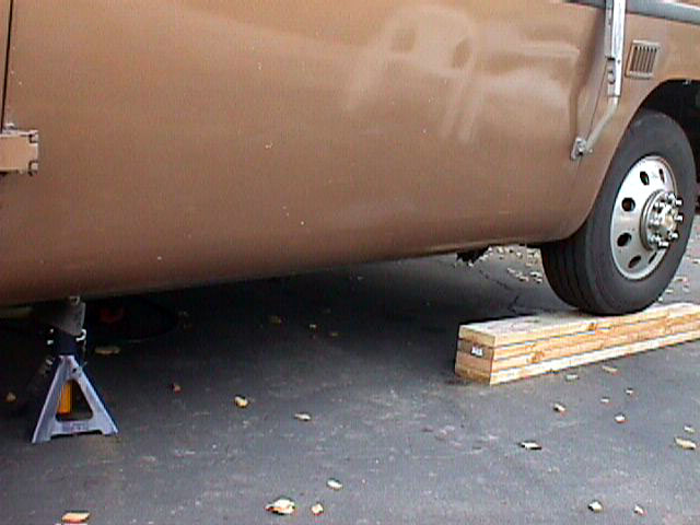
This is the start of a
Howell TBI installation.

These are the parts to be added.
 Need to get under the wheel
wells
and do some work
so it is suggested to raise the front of the coach. I feel safer
with it up on blocks and this was enough height. This picture
shows that it is necessary to put a block or stand under the rear of
the GMC when ever you are under the rear. There is nothing lower
than a GMC if an air line or bag
breaks.
Need to get under the wheel
wells
and do some work
so it is suggested to raise the front of the coach. I feel safer
with it up on blocks and this was enough height. This picture
shows that it is necessary to put a block or stand under the rear of
the GMC when ever you are under the rear. There is nothing lower
than a GMC if an air line or bag
breaks.
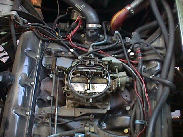
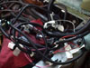
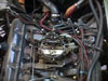 Time to get rid of some of this
clutter. Ready
to remove carb, christmas tree, and gas pump. It is interesting
what you find when you go looking. I found a bolt on the AC
compressor bracket that was finger loose. I found a vacuum hose
that was barely on a source connection that I know was on before.
Might have been blown off by a backfire ?? Reminds me that we
should be looking all the time for these sorts of problems. This
is a definition of Maintenance.
Time to get rid of some of this
clutter. Ready
to remove carb, christmas tree, and gas pump. It is interesting
what you find when you go looking. I found a bolt on the AC
compressor bracket that was finger loose. I found a vacuum hose
that was barely on a source connection that I know was on before.
Might have been blown off by a backfire ?? Reminds me that we
should be looking all the time for these sorts of problems. This
is a definition of Maintenance.
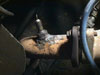
 This is a picture of the dreaded
input filter to the
Quadrajet. Mine was loose ( but not stripped like some).
The pipe connector
is shown just to the right of the filter. Note the nicely rounded
corners of the nut from many in-the-field removals by previous
owners.
The last person to remove this gas line was a Mechanic in Mexico with
the
largest vice-grip pliers I have ever seen. I took a hint
from
him and I used the same to remove this for the last time.
Gone,
gone forever.
This is a picture of the dreaded
input filter to the
Quadrajet. Mine was loose ( but not stripped like some).
The pipe connector
is shown just to the right of the filter. Note the nicely rounded
corners of the nut from many in-the-field removals by previous
owners.
The last person to remove this gas line was a Mechanic in Mexico with
the
largest vice-grip pliers I have ever seen. I took a hint
from
him and I used the same to remove this for the last time.
Gone,
gone forever.

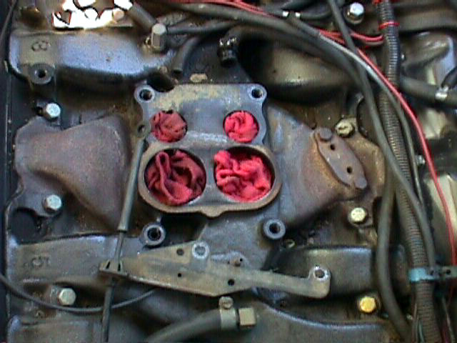
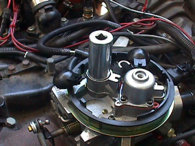
All cleaned off and ready to install the adapter plate and TBI.
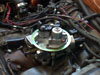
TBI installed, everything fit great so far. I had to add some RTV
to the lower passenger side of the adapter plate. This is as per
instructions. Now to crawl under the old gal and install the
injector pump and filter.
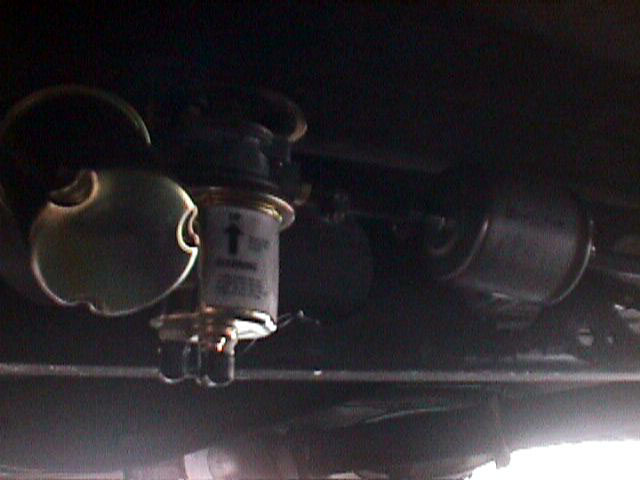
 The object on the left is a spin
off filter that is
attached to the selector valve. The next object to the right is
the low pressure booster gas pump. This pump is here because
there is a strong feeling in
the GMC community that the GMC sucks air at low gas levels in the
tanks, and that there is a need for a high volume pump to feed the
pressure pump of the quadrajet or the TBI. The third object to
the right is another filter. This filter is to take out any
remaining small particles that might plug an injector and to provide a
small reservoir. Jim Kanomata and others say that when the GMC
sucks air from the fuel tanks there needs to be a reservoir to keep the
air bubbles out of the injectors. I hope these two filters will
provide enough storage and will let the air bubbles dissipate.
The Howell kit only recommends the one high pressure pump.
The object on the left is a spin
off filter that is
attached to the selector valve. The next object to the right is
the low pressure booster gas pump. This pump is here because
there is a strong feeling in
the GMC community that the GMC sucks air at low gas levels in the
tanks, and that there is a need for a high volume pump to feed the
pressure pump of the quadrajet or the TBI. The third object to
the right is another filter. This filter is to take out any
remaining small particles that might plug an injector and to provide a
small reservoir. Jim Kanomata and others say that when the GMC
sucks air from the fuel tanks there needs to be a reservoir to keep the
air bubbles out of the injectors. I hope these two filters will
provide enough storage and will let the air bubbles dissipate.
The Howell kit only recommends the one high pressure pump.
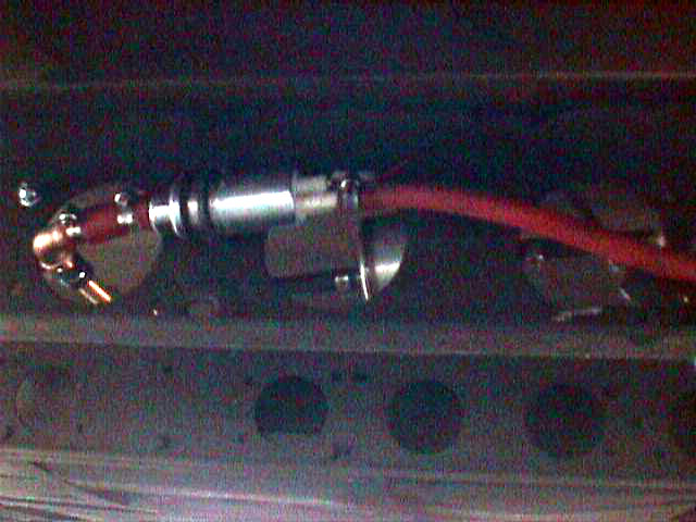
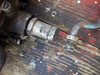
 This picture could be labeled "
why use one when two
will do?". This is the high pressure gas pump for the
injectors. this pump supplies 12 to 20 pounds of
pressure. I might move this pump closer to the engine in
the future. It would be a good idea to carry a spare pressure
pump, the pump as a Airtex E8228. Howell gets $112 for
it.
I found it on the net at expressautoparts.com for $94.52 and if we were
to
search more we could probably find it for less. Emery.
This picture could be labeled "
why use one when two
will do?". This is the high pressure gas pump for the
injectors. this pump supplies 12 to 20 pounds of
pressure. I might move this pump closer to the engine in
the future. It would be a good idea to carry a spare pressure
pump, the pump as a Airtex E8228. Howell gets $112 for
it.
I found it on the net at expressautoparts.com for $94.52 and if we were
to
search more we could probably find it for less. Emery.
Here is an alternative install location for the Electric pumps and
filters used by Emery Stora
http://community.webshots.com/album/55385018UnYHdd
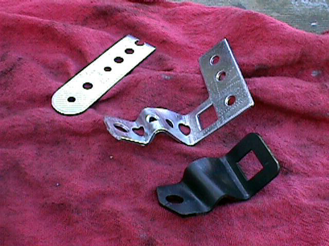
 So much for
buying a kit with everything there. My Rostra
cruse control needs a bracket also, so I cannot use the one that came
with
the Howell. The bright wiggly piece of metal is the bracket I
made
with the piece sent by Rostra. Looks like it will work well.
So much for
buying a kit with everything there. My Rostra
cruse control needs a bracket also, so I cannot use the one that came
with
the Howell. The bright wiggly piece of metal is the bracket I
made
with the piece sent by Rostra. Looks like it will work well.
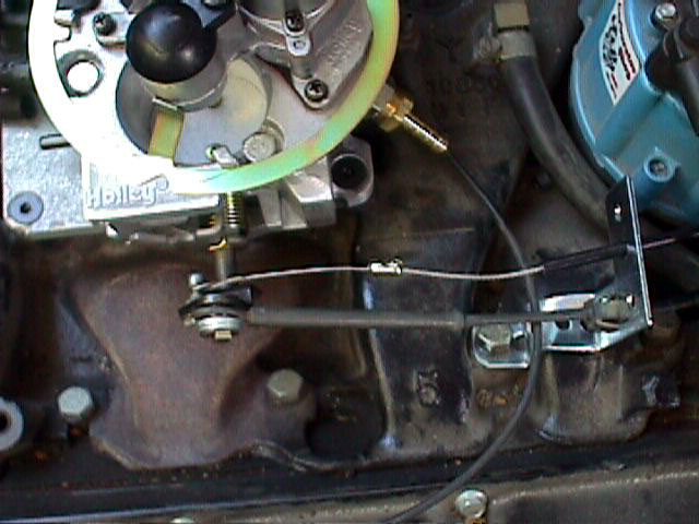
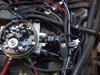
 I took the cruse control
ball joint from the
Quadrajet and
the final assembly looks like it will work. You can see the
difference on my web page under Rostra.
I took the cruse control
ball joint from the
Quadrajet and
the final assembly looks like it will work. You can see the
difference on my web page under Rostra.
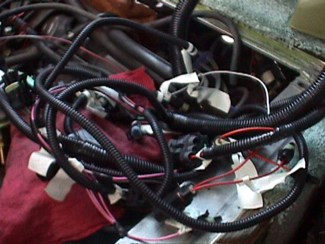
 Lets see now,
the ankle bone connects to the hip bone,,, no the hip bone connects to
the knee bone,,,, well it looks bad but is really easy to route the
harness. I was a little miffed when they said connect the grounds
to a bolt on the rear of the head. But they did not
supply the bolt.... 20 minutes scrounging for a bolt and lock
washer. Then they said use 3 ea 1/4 inch washers on the
throttle control..... you guessed it, no washers. Another 20 min.
looking for right thickness washers. Small things but gripe
you all the same.
Lets see now,
the ankle bone connects to the hip bone,,, no the hip bone connects to
the knee bone,,,, well it looks bad but is really easy to route the
harness. I was a little miffed when they said connect the grounds
to a bolt on the rear of the head. But they did not
supply the bolt.... 20 minutes scrounging for a bolt and lock
washer. Then they said use 3 ea 1/4 inch washers on the
throttle control..... you guessed it, no washers. Another 20 min.
looking for right thickness washers. Small things but gripe
you all the same.
 I guess this hole is to let the
mice in..... I hope
they give me
a plug to cover this hole into the cab. The computer mounts on
the
end of the cable through this hole..... Dam big hole.
I guess this hole is to let the
mice in..... I hope
they give me
a plug to cover this hole into the cab. The computer mounts on
the
end of the cable through this hole..... Dam big hole.
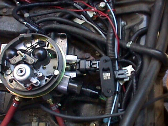
 My map sensor was mounted underneath
passenger
seat. But I
moved it to top
My map sensor was mounted underneath
passenger
seat. But I
moved it to top
of engine as per Howell. Troy of Howell said it should be as
close to TBI as possible.Jerry
The instructions say to mount the MAP sensor on the rear flange of
the engine compartment..... Wire is too short. The answer seems
to be mount the MAP sensor as close to the vacuum source as
possible. I mounted mine with the vac connections down and I used
a cable tie to attach the
sensor to pipes and cables near the TBI. I connected the vacuum
connection to one of the sources on the front of the TBI. The
instruction sheet is in error when it says to use a vacuum connection
on the rear of the
TBI.
 I chickened out on the O2
sensor, I had it
welded in for me...I hope I don't need headers for a while.
I chickened out on the O2
sensor, I had it
welded in for me...I hope I don't need headers for a while.
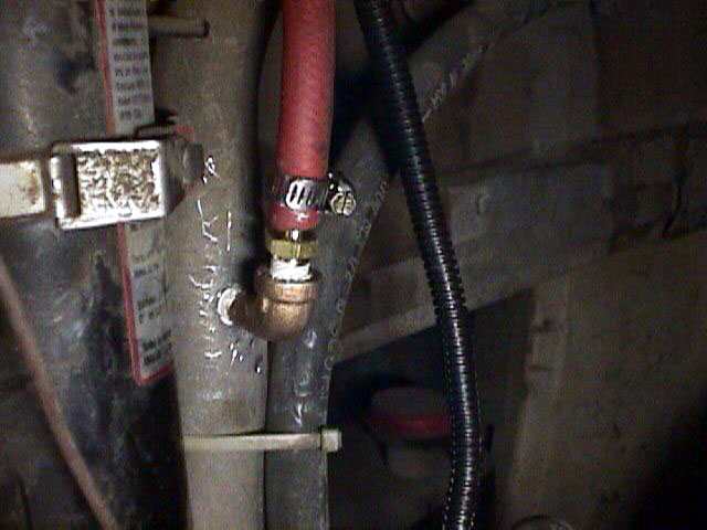
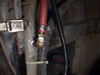 This was the part I did not
look
forward to
installing. I did not want to punch a hole in the gas fill pipe
and put an obstruction in the already slow filler tube.... Sigh, I
could find no better place so as per the instructions, I used a punch
to make a hole in the pipe and then put in 1/8 pipe threads and the
barb fitting. The hose goes to the return from the TBI. It
went ok, I did not put a spark into the tank and
I did not blow up.
This was the part I did not
look
forward to
installing. I did not want to punch a hole in the gas fill pipe
and put an obstruction in the already slow filler tube.... Sigh, I
could find no better place so as per the instructions, I used a punch
to make a hole in the pipe and then put in 1/8 pipe threads and the
barb fitting. The hose goes to the return from the TBI. It
went ok, I did not put a spark into the tank and
I did not blow up.
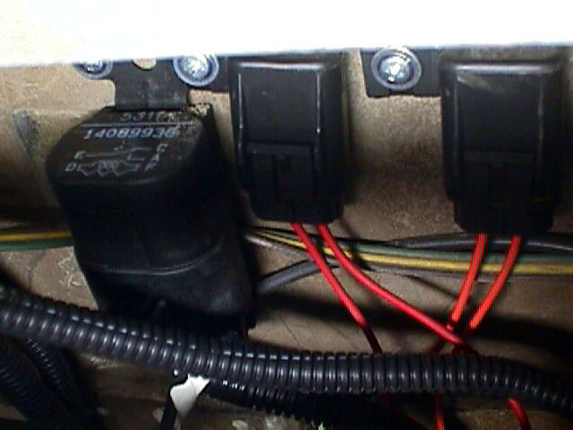
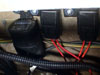 Mounted the fuel pump relays to the
rear of the fire
wall.
Was a good thing I remove the old cruse control, this gave room for
these
to be mounted. Now on to the final wiring. When routing the
electrical connections to the TBI, be sure none of them are placed
above
the old wires. Space is critical on top of the engine and the new
cable harness will get in the way of the air cleaner
Mounted the fuel pump relays to the
rear of the fire
wall.
Was a good thing I remove the old cruse control, this gave room for
these
to be mounted. Now on to the final wiring. When routing the
electrical connections to the TBI, be sure none of them are placed
above
the old wires. Space is critical on top of the engine and the new
cable harness will get in the way of the air cleaner
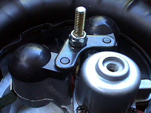
 It is not clear from the
instruction sheet, but the
Air Cleaner hold down bolt they supply replaces the bolt that holds
down the injectors. You will have to cut down the threaded rod
and I added a Nylock nut at the right height to hold in the
injectors. This is critical since the
small bracket that holds in the injectors can fall off when the Air
Cleaner
is removed and fall into the intake manifold.
It is not clear from the
instruction sheet, but the
Air Cleaner hold down bolt they supply replaces the bolt that holds
down the injectors. You will have to cut down the threaded rod
and I added a Nylock nut at the right height to hold in the
injectors. This is critical since the
small bracket that holds in the injectors can fall off when the Air
Cleaner
is removed and fall into the intake manifold.
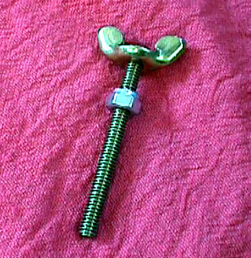
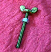
 The Nylock nut holds down the
injectors while the
wing nut holds
on the Air Cleaner. I removed the vacuum lines from the Air
Cleaner. The Howell supply's more gas for a cold start so the
warm air should not be needed for starting.
The Nylock nut holds down the
injectors while the
wing nut holds
on the Air Cleaner. I removed the vacuum lines from the Air
Cleaner. The Howell supply's more gas for a cold start so the
warm air should not be needed for starting.
TESTING
INJECTORS
My injectors were plugged when I first tried them. Howell says
the goop Holly ships inside the injectors causes this problem and
Howell
suggested tapping them with a wood screw driver handle. I tapped
every thing in the area and finally one of the injectors started.
I removed the other one and by shaking and tapping I got it to
go.
When you replace the injector, it is necessary to seat it into the
holder.
This is done by placing a socket over the injector and taping lightly
with
a hammer. This will seat the injector and the two O rings.
See the picture below.
 You can test to see if pulses are
going to the
injector by using
a 12 volt test light between the two connections in one injector
cap. When you crank the engine you should see the light
flash. The pulse for the injector comes from the tach signal to
the computer. If you do not get pulses at the injector, make sure
you are getting a good signal from the tach input. I used my tach
to determine this signal was
present.
You can test to see if pulses are
going to the
injector by using
a 12 volt test light between the two connections in one injector
cap. When you crank the engine you should see the light
flash. The pulse for the injector comes from the tach signal to
the computer. If you do not get pulses at the injector, make sure
you are getting a good signal from the tach input. I used my tach
to determine this signal was
present.
Fuel Lines
The Howell system comes with rubber fuel lines to and returning from
the TBI. We have never felt comfortable with these rubber lines
over
the engine. Emery was the first I know of that put
flexible stainless shielded Teflon lines to his
TBI. Manny converted his last year and promised to help Mr.C and
me to get lines for ours. We had
the return flex line made 4 feet long so that it would reach to the
fill tube where the return line is attached. The Feed line is 18
inches long and reaches to the firewall where we attach to the line to
the injection pump.
http://www.gmcmhphotos.com/photos/showgallery.php?cat=3112
These pictures show the lines we had made a Royal Brass. Manny
found their lines and service to be excellent and Mr.C and I had two
sets made. The rubber return line from my TBI was cracked and
getting stiff after
less than a year. This made it clear that the rubber lines are
not
a good idea.
I would recommend any one with these systems replace the
Rubber lines with some sort of a metal sheathed flex line.
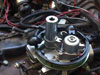
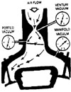
Hooking up the Vacuum
CLICK ON THE PICTURE FOR DETAIL
The way mine is set up now, and according to troy at howell, is :
the left front port goes to the MAP sensor
The center top one goes to the pcv valve etc,
the center bottom one goes to the distributor, and
the right one goes to the canister.
Here is a picture of my setup. It is just like the list above
except I have the MAP senson on the manifold
Click
Here for the Picture of the Engine Vacuum Connections
To verify the types of vacuum on your system, connect a vacuum
gage. With the throttle closed, if there is vacuum, you are
attached to Manifold Vacuum. If you only get vacuum when the
throttle is open, you are attached to Ported Vacuum.
There is a CHANGE IN THE INSTRUCTIONS FROM HOWELL.
DO NOT USE the port in the back of the TBI unit for
the MAP vacuum any longer, the best location is in the front of the
unit or
from a separate manifold vacuum source.Troy
The latest word from Howell is that the TBI left and right vacuum
connections are hard vacuum while the lower center one is ported
vacuum. They
also say the vacuum advance for the distributor needs to be connected
to
ported vacuum. This is different from the included
instructions.
The way mine is set up now, and according to troy at howell, is :
the left front port goes to the MAP sensor
The center top one goes to the pcv valve etc,
the center bottom one goes to the distributor, and
the right one goes to the canister.
Here is a picture of my setup. It is just like the list above
except I have the MAP senson on the manifold
Click
Here for the Picture of the Engine Vacuum Connections
As Emery points out the GMC manual says the original equipment
distributor is connected to PORTED VACUUM when the engine is cold
and MANIFOLD VACUUM when the engine is very hot using the TVS valve.
-------------------
I hate TVS. Period. I've eliminated this system on every
car I've had that uses it and gone to a ported
vacuum source.
Using ported vacuum, which is from a source located above the
throttle plates, the advance mechanism in the distributer is allowed to
move to suit the demands of the engine. When vacuum levels are
high, as in part
throttle cruising, you have max advance. When vacuum levels are
low,
as when the engine is under heavy load, you have little or no
vacuum
advance and the engine operates under initial advance, which is what
you
set with a timing light.
There is an old trick that still works better than anything other
than a dyno for setting initial advance, (or timing as
it's etime called), and that is to set your initial
advance to the factory setting and test it under maximum load.
Usually a long grade or steep hill. If you detect engine
detonation, retard the timing a degree & try again. Repeat
this until there is no longer any pinging during your testing.
This is the optimum setting for your engine. The other side of
this test is if there is no detonation at the factory setting, add a
degree and try again. Still no pinging? Add another and so
forth. Bear in mind however, that this method only works when the
TVS is by-passed and you are using a ported source of vacuum for the
distributer. Also, take a moment to test the vacuum advance
mechanism by using a hand pump
(MityVac) or sucking on the vacuum line to the distributer while the
engine
is idling and note the increase in idle speed. If there is an
increase
with the application of vacuum and subsequent decrease when you remove
the
vacuum, rest assured that the distributer vacuum advance is working
properly.
It's tough to accomplish more than this without using the costly dyno
method. To answer your original question about the plate
movement; With no vacuum signal present, the mechanism rests
spring-loaded against a stop.
The vacuum signal overcomes the spring tension and moves the plate.
Vacuum
applied to the distributer will advance the timing, not retard it.
There is one other advance mechanism in the distributer that
adds into the overall equation and it is called "mechanical"
advance.
I won't go into that here since your concern seems to be with the
initial
and vacuum side of the house and also because working with mechanical
advance requires the use of some specialized equipment.
BTW, a quick check for a "ported" source of vacuum is to use a gauge
to test all of the ports on the carburetor (above the base plate) while
the engine is idling. When you find one that registers zero at
idle & increases as you advance the throttle, you've found your
source.HTH,Steve Ferguson
---------------------
Click
on Picture for larger picture
PORTED VS
MANIFOLD VACUUM
PORTED VACUUM
Is obtained from a passage just above the
closed throttle. At idle, no
vacuum is applied this port due to its location. As the
throttle is opened, this port is exposed to manifold vacuum, so vacuum
at this port begins to increase.
MANIFOLD VACUUM
The manifold vacuum signal is high at idle and even higher when
decelerating at relatively high engine speed with the throttle valves
closed. At sea level, the idle manifold vacuum is usually in excess of
20" HG.
------------------
SETTING THE IDLE
This is a simple but critical adjustment covered briefly in the
Howell instructions that at first I did wrong because I did not under
stand the sequence of the adjustments.
The computer adjusts the idle depending upon RPM, throttle position,
temperature and other conditions. The computer controls the idle
using
a small stepping motor that adjusts the idle air control.
What this procedure does is to run the stepping motor to one end of
its' travel and then you manually set the warm engine idle as a
starting point
to give the stepping motor enough range of control for all conditions.
The following setup procedure must be followed exactly: ( I did
not understand this)
Warm up the engine
Turn off the key and stop
the engine
Place the jumper
between the A and B connections on the diagnostic connector.
Turn on the key but do
not start the engine
(the stepping motor will now go all the way to one end of its' travel
and you will be able to hear it clicking when it has reached the end)
Remove the four conductor
cable from the idle air control stepping motor
(the stepping motor is now positioned and removing power will let it
stay there during adjustment)
Start the engine
Adjust the idle speed screw
located near the throttle control to set the low idle speed
( set the RPM so the warm engine will idle with out help , should be
about 650 RPM)
Turn off the key and stop
the engine
Replace the stepping motor
connector and remove the jumper from the diagnostic connector
The engine should now start and run on idle under computer
control. You should not have to help the computer make the engine
idle and the engine should not stall when you remove your foot from the
gas peddle. My engine idles at about 1000 RPM under open loop
computer control.
--------------------
AIR FUEL GAUGE
The Air Fuel Gauge has been installed. The calibration of the instrument shows me the
14.7 to 1 opimum reading should be in the green area of the
meter. I have mounted the CHECK ENGINE LIGHT on the
dash near the meter with the test switch so that if the light
comes on during driving conditions, I can push the switch and "read"
the light to see if the computer has gone out of lock.
I am going to use this meter to set the fuel pressure to the injectors
as described by Jerry below.
JERRY'S ADDITIONAL
SUGGESTIONS
I do have a few suggestions or maybe I should call them
observations.
1. That RTV patch on the adapted plate is critical.
There is
nothing under
that area to support the RTV so you have to use quite a bunch in order
for
it to seal.
2. Be sure to also plug the unused mounting holes in that
plate with
RTV.
3. I had the cruise control bellows that used a rod instead of
chain linked
to the throttle. I removed that and adapted to chain. The
throttle cable and cruise rod crossed. Gas pedal was sticky.
4. Right rear vacuum connection on TBI is ported.
According to Fellow from
Howell, should not be used. Plug it off.
The port in the back of the TBI unit must not be used for the MAP
vacuum any
longer, the best location is in the front of the unit or from a
separate
manifold vacuum source.Troy
5. On the TBI between the injectors is the fuel pressure
regulator. Preset
from Howell at Approx. 12 lbs. I use a fuel/air ratio monitor
permanently
installed . With it I adjust that pressure to get fairly constant
14.2 of
14.7 (can't remember right now which).
6. I do not at present have a knock sensor but maybe Santa is
listening. I
adjusted my timing to get a total advance of 36 degrees. Turns
out that is
about 9 degrees fixed on the dist.
7. When installed they had to change out my fuel tank
switching
valve. Said the fuel pump kept sucking it open and causing it to
suck air.
Never did fully understand that.
8. This fuel pump returns unused fuel to tank via the fill
line. If I had
known I would have had installed a line from TBI back to rear
instead
a fill tube. Had no problem just don't like it.
Please let me know if I can be of any help. Jerry
-------------------
SUGGESTIONS BY EMERY STORA
The throttle body and injectors are stock Holley and are the same
ones that are on the Holley kit that I installed in 1993.
A couple of suggestions: I put the gasoline return line into
the rubber hose (about 1: in diameter) that leads to the gasoline
filler tube. I used a solder type rigid copper fitting that fit
the ID of the hose and that had a small copper stub that the smaller
hose would fit on. This saved me the drilling and tapping of the
metal fill tube.
I have never liked fuel hoses. They crack over time and can
cause an engine compartment fire. I connected to the steel fuel
line that runs along the front crossmember and then I ran a 3/8" steel
line from the right front frame, along the frame to keep it away from
the exhaust and
to the right rear
of the motor box and then forward over the engine to the throttle
body. If you remove the injector mechanism you will see how they
have a hose barb fittings (inlet and overflow return) screwed into the
throttle body injectors. I replaced the hose barbs with brass
fittings that would accommodate direct connection to the metal gasoline
lines, thus eliminating the hoses.
I still have a hose going from the rear tanks along the frame rail
to the
front tube that goes along the front cross member but plan to replace
most
of this hose next spring. Most of the rubber deterioration occurs
where
the heat is. That is why I didn't want any hose over the engine.
My
second gasoline filter is a large metal can type that came with the
Holley and is at the passenger right front frame and is easily
accessible. It presently has two small sections of hose hooking
it to the gas lines, but I am planning to look for a similar high
capacity metal filter with fittings so as to eliminate those two short
hoses. I could also just use brass fittings with compression
rings on the filter if I don't find a suitable
filter with fittings.
To adjust the fuel pressure at the injectors (Holley say about 18
psi) you'll need a fairly accurate fuel pressure gauge. I have
found that you can purchase a relatively inexpensive dial type air
pressure gauge (0 to 50 psi) and unscrew the tire gauge fitting on the
end and clamp a hose to it. The one I bought was under $5.00 at
Pep Boys. I tested it for accuracy before using it on the TBI
system and it was right on in
the range I wanted.
I originally went to the Holley TBI system because I had just moved
from the San Francisco bay area (sea level) to Santa Fe (7000 ft.) and
my GMC performed terribly. The TBI took care of all the problems
that I was having with the carb at that time and has given me
relatively trouble free service over the years. I have used it
across the country several
times in all types of temperature, altitude, and terrain and feel that
it
is the best modification I have made to the GMC (6 wheel disk brakes
are
a close second).Emery Stora
FREQUENTLY ASKED
QUESTIONS BY
PAUL
1. How far from the end of my exhaust Doug Thorley headers is
the oxygen
sensor installed? My headers are coated with a metallic ceramic
coating.
If the sensor can be installed in the short extension tube , running
from
the end of the header to the muffler, then I can have it re-coated,
since I
assume that the bung will need to be welded in place?
Since the sensor has to see the exhaust from the whole bank I
would guess it would mount like on my standard manifolds about 3 inches
from where all the exhausts converge.
2. Is there any advantage to installing an oxygen sensor in
each header?
I guess it could, however program in the computer would have to
be changed.
3. What is the make, model, and CFM rating of the throttle
body?
675 CFM Holly ProJection 2
What make and model fuel pump comes in the kit?? What psi
rating is it??
about 14 to 20 pounds
Does it mount outside the fuel tank?
on the frame in front of the tank
4. Where do you recommend locating the:
a. Computer? Any problem with it
being located in the engine
compartment? If inside the interior of the coach, what size hole
is needed
to be cut into the floor?
Under the passenger seat and it is a 2 -1/8 inch hole
b. Fuel pump fuse holder, relay, and
ESC.
on the fire wall
5. Other than what you told me earlier below about an optional
available
knock sensor, et., are there any other optional TBI parts/components
available from you that I may want to consider for my installation?
They have a fuel pressure gauge
Our fuel pressure gauge is for tuned-port injection only. You would
have to get one from a parts store, a 15 psi gauge is used in this
system and locate the gauge between the TBI unit and the fuel pump
anywhere in
the line, preferably closest to the TBI unit or extend it out into the
Cab.Troy
6. Do you have anything available that will show the engine
check light?
I'd like to do some planning for layout on my instrument panel if I can
get
details on its overall size.
They don't supply the light, just say to use a 12 one. I am
going to use one on a switch so I can switch on the diagnostic mode on
the fly.
Apparently the alternator used on our coach is thought to be the
source of
electrical/RFI problems that's affecting one of the port fuel injection
(PFI) systems a number of people have installed on the GMC Motorhome.
Theory I heard is that unlike ours, the new car alternators have
circuitry
that is compatible with the electronics of the fuel injection
system? Are
you aware of any voltage spike and RFI problems caused by the
alternator
used on our engine, affecting your kit operation?
Hummmmm
7. Will there be any conflict with the accelerator cable
mounting bracket
being in the way of connecting the gas and vacuum lines to the throttle
body
in my vehicle application?
Nope they have that taken care of.
8. Does your kit include:
a. Appropriate fittings (e. g. a "T")
for both the oil pressure and
the water temperature senders so that I don't have to go out and get
them?
Yes they do
b. Fuel pump power supply wire, which
would need to be routed to the
pump located just in front of the driver side rear wheels.
c. Fuel pump fuse holder.
d. A wiring harness having adequate
length and sufficient slack so
that I can position it to all the components on the engine without
stretching some of the components, which then are hard to mount where
they
belong?
This seems to be good, they supply all that is needed
e. A diagnostic connector?? If
so, what type? Where does it mount?
with the computer under the seat
f. PROMs optimized for the GMC
Motorhome having a 403 cid engine.
yes
g. Vacuum plugs to plug any unused
throttle body port.
they seem to use all of them.
h. Fittings on the throttle body with
sufficient tubing length to
hookup the fuel supply and return lines/hoses.
Yep if you like rubber fuel lines
i. Distributor switched power supply
wire.
got it
j. Terminal to connect wiring to a
computer controlled distributor
that matches the type (GM) needed.
No they do not do this on the one I am using
k. A "block off" plate to cover up
the well
opening in the intake
manifold exposed by elimination of the carburetor choke heat pick up
pipe.
No, Mine was already covered, I am not sure how this works
l. Any items of other than new parts?
nope all seem new, Maybe the computer ?
9. What parts will I require in addition to what you supply to
hook up the
system on my GMC motorhome?
3 ea 1/4 in washers and a 3/8 bolt so far
10. Are there complete, detailed installation instructions,
specific for my
vehicle application? If so, do they address each of the
following:
a. Hookup to the fuel evaporative
canister.
Unchanged
b. Existing heat tube
from the
exhaust manifold-to-air cleaner
housing and the vacuum hose to the air cleaner air entrance throat
valve
that controls heat into the carburetor.
not sure yet
c. Dimensions, etc., for
mounting the accelerator cable to the
throttle body in order to get full throttle opening.
Yes and a bracket
d. How to secure the
accelerator cable bracket in place.
same as above
e. Type and size of hose
to use for the gas return line.
supplied
f. Need to calibrate the
system once it's installed? If so, what
equipment does one need to do that?
See the notes above from Jerry
g. Vacuum line
connections and
plugging.
no
h. Computer controlled
distributor wiring.
no
i. Any unused wires found
in the wiring harness.
no
j. Bungs for mounting the
oxygen sensors. How many oxygen sensors
are included?
one
k. A complete system
wiring schematic, including the distributor.
Nope just the GMC manual
l. Where to route and how
to connect the fuel return line back to
the gas tank.
yes
11. Can I use the original engine compartment cover or do I
have to raise
it to clear any increase in height from the TBI system.
Same cover
12. Do you have available an engine analysis of the before and
benefits
after installing the TBI kit? Can I get a copy of it to look at?
Paul
From: Troy Brown [tbik@advnet.net]
? Any reason I can't furnish the distributor (e. g. a 81-85 Olds V-8
one)?
Are you saying a different Esc module (what does Esc stand for?) is
required
with the knock sensor?
You may furnish the distributor if you like, 81-85 Olds V8,
computer
controlled distributor.
ESC stands for Electronic Spark Control, the ESC module from a
computer
controlled ignition system is required along with the knock sensor.
? If one opts for a non-vacuum operated distributor, what additional
parts are
required?? What would the price be then??
Is there any lights or controls that need to be mounted adjacent to the
driver?
The price of the kit is $1200 , $275 for the distributor, coil,
and coil
connector and jumper. The knock sensor is $45 and the Esc
module is $60.
The only light there is, is the check engine light in which you
would mount
to the dash.
?Does your system control fuel delivery and control the spark??
Yes our system controls fuel delivery, but it does not control
spark.
However, we can control the spark if you would like to change
the
distributor.
I'm interested to know how your TBI system for a GMC Motorhome with
a
403
cid engine, compares/differs from the TBI system that Turbo City
Our system is the same as Turbo City except for; our system
allows you
to
maintain your HEI vacuum advance distributor. We have
customized the chip
to eliminate the original computer controlled distributor
system. This
system is similar to the 87-90 GM 2 bbl TBI systems using GM parts
except
for the throttle body and fuel-pump. The cost is : $1.200.
ELECTROINC SPARK
CONTROL
If anyone is interested in what is involved with changing over to
ESC (electronic
spark control) this is where I am at so far.
Had to remove my TBI harness and send it and the ECM back to Howell.
They are going to rework the harness and trade out the ECM. I
have to
pay $75.00 to burn a new chip for the ECM and $30.00 for new connectors
on the harness.
I received a package yesterday containing:
Distributor.........$300.00
Coil (remote)......$40.00
ESC module......$60.00
Knock Sensor....$45.00
They are all new GM parts. Yup, thats $550 invested minus $225 for
the HEI being sold, so the upgrade is costing me $325 plus tax,
shipping,etc. One could probably shop and find parts cheaper,
especially if parts from the salvage yards were used. I just like the
idea of all my engine electronics
coming from one source with the comfort of having technical support
just in case something goes haywire. When I get my harness and ECM back
(shipped out yesterday), I will get it all installed and let you know
how it runs.
The engine starts easily without even touching the pedal. It idles
as smooth
as glass. The throttle response is crisp without even a hint of stumble
or
hesitation. These features alone made this project
worthwhile for me. Now, if I get a little added economy and / or
performance, then that would be an added bonus. I do expect some
increase in engine longevity with the electronic controls as well.
The change from HEI to HEI / ESC will end up costing me about $200.
If there is a 1/4 MPG increase, then at $1.40 / gal for gas, I figure
the
ESC will pay for itself in 70 K miles. The 1/4 MPG is purely
speculatory,
but the point is, depending on coach usage, I don't think that the
change
to ESC
alone will have economical pay offs. But, for the benefits mentioned
above, I still recommend the change. Dave Meekhof
Training Manual
for an EMIC ESC system
CUSTOMER SERVICE
I am happy to report that outstanding customer service is alive and
well at Howell Engine Development in Marine City Michigan. I
experienced it last Friday.
After driving all night from Eastern Ohio to Marine City without
incident, my brother and I talked with a couple of fellow GMCers while
Troy Brown looked over my TBI to find an intermittent problem that I
had been unable to locate for some time. He found it
(intermittently faulty ground) and while he was at it, reprogrammed the
computer chip to fatten up the mid-range performance and went through
the entire system. This included test drives
with a scanner installed to read the system perf ormance under various
driving
conditions. We then left for the 350-mile return home. South of
Detroit, near the I-275/I75 junction, the engine suddenly died and we
were unable to restart it. I called Troy and he went through
several checks over the phone, to no avail. He then said he would
be there in about and hour and a half. We turned on the roof air,
relaxed, and waited. When he arrived, he had with him a box of parts to
cover every possible problem. It turned out to be unrelated to
the fuel injection system
itself -- a failed ignition coil. We took the cap/coil from the
complete distributor that he had brought, installed it and were on our
way without further incident. In addition to offering an
excellent product, this company is made up of people who do what it
takes, and much more, to serve their customers.
Until Friday, I wouldn't have believed it. Drop me an email if
you would like to know more.Terry Wallace
Smog
testing
I also have Thorley headers, that does have a California waiver, but
there is only one place here in San Diego that I know of, Juan's in San
Marcos, that will smog a GMC with both mods. I have had mine smogged
there three times.
I would have to sell my GMC out of state if it weren't for Juan's. I
don't have the mechanical fuel pump, carb or air cleaner, sure wouldn't
be easy to borrow a set up every 2 years. So there are places that will
smog GMC's with fuel injection, just ought to
ID them before you install it.
Regards, Gene 76 Eleganza, Vista, CA
GMC REFERENCES
Manny
Mr.C
Emery
Dave
Gene
[INDEX] | [SUGGESTIONS]