[KNOCK SENSOR]
[COMBUSTION ANALYZER] [TEMPERATURE
MONITORS]
[DIGITAL VOLTMETER] [BATTERY
CHARGE MONITOR][A/F EXAMPLE]
COMBUSTION ANALYZER
AIR / FUEL RATIO GAUGE
I always thought there was some mysterious circuit needed to make
this measurement. The reference below explains that the O2 sensor
GENERATES a voltage that you can measure. This voltage is a
comparison
of the oxygen inside the exhaust and the oxygen in the outside
air.
There are even self tapping sensors
that
do not have to be welded into the exhaust pipe. If you measure
this
voltage with a high impedance digital voltmeter, you will get readings
:
1.1 volts (rich)
0.45 volts (proper ratio 14.7)
0.2 volts (lean)
The optimum reading is 0.45 volts which is 14.7 parts of air to one part of fuel. This voltage is not going to sit still so what you are really going to read is the average of this voltage and watch to see if you are generally running rich or lean.
ANALOG O2 METER
 After
using the Digital indicator from JC Whitney for about a year, I found I
did not like the bouncing lights and that I was never sure I trusted
that
the digital instrument was always working because it would go off at
times.
Turns out, it was working just fine it was JUST that I always had to
interpret
what it was telling me.
After
using the Digital indicator from JC Whitney for about a year, I found I
did not like the bouncing lights and that I was never sure I trusted
that
the digital instrument was always working because it would go off at
times.
Turns out, it was working just fine it was JUST that I always had to
interpret
what it was telling me.
I guess I am just an analog guy so I bought this meter from Westach (http://westach.com) and I like it much better. The TBI (ECM) computer still moves the readings around, but this damped meter shows the actual voltage reading from the O2 sensor. They make these meters one at a time and I have seen them calibrated at the factory so I know they are accurate. The cost was similar -- less than $40 with shipping.
DIGITAL O2 METER
 JC whitney sells a bar graph meter (81tb5401x--$36) that will provide a
continuos display of this voltage , the cost is $36.00. I
want
to watch this reading all of the time, so I am going to read this
parameter
with the meter shown. The meter is made by Intellitronix
Corp. The inside of the meter is made from integrated
circuits
as you might expect so therefor the meter requires 12 volts supplied
from
a switched or Accessory source. The colored bars represent .1 volts
per
bar with the magic 0.45 optimum reading located in the two center
(green) bars. My meter calibrated out like this:
JC whitney sells a bar graph meter (81tb5401x--$36) that will provide a
continuos display of this voltage , the cost is $36.00. I
want
to watch this reading all of the time, so I am going to read this
parameter
with the meter shown. The meter is made by Intellitronix
Corp. The inside of the meter is made from integrated
circuits
as you might expect so therefor the meter requires 12 volts supplied
from
a switched or Accessory source. The colored bars represent .1 volts
per
bar with the magic 0.45 optimum reading located in the two center
(green) bars. My meter calibrated out like this:
VOLTS
RED
1.04
RED
0.96
YEL
0.85
YEL
0.75
GRN
0.62
GRN
0.53
YEL
0.42
YEL
0.32
RED
0.21
RED
0.11
The bars light from the bottom up so that when the engine is running at the optimum Air Fuel Ratio, all of the bars from the bottom up through the green bars will be lit.
So far the meter has shown how hard the computer in the Howell TBI system is working. With a cold engine at 2000 rpm, with the computer locked in closed loop operation, the readings are going all the way from the bottom reds up through the top two yellows. The lights go up and down very fast showing the computer is working very hard to keep the engine at rpm. The engine sounds smooth but if you listen while watching the meter, it is possible to hear the variation in engine sounds that go with the meter readings. It is fascinating to watch the computer work.
SENSOR MOUNTING
1. closer is not necessarily better. Oxygen sensors have a operating range from about 300 degrees centigrade to 950 degrees centigrade. It is possible to get the sensors too close to the head and melt or damage them with excessive heat.
2. There are two possible reasons for a heated oxygen sensor. One is to get the injection system into the clean running closed loop mode sooner for EPA cold start testing. The second reason is if the sensor is too far from the manifold it may drop below operating temp at idle.
3. In a closed loop emmissions system the oxygen sensor returns rich-lean information to the vehicle computer, by nature the oxygen sensor is always a little behind real time. If the O2 sensor is far down the exhaust pipe the sensor is placed further behind.
4. If you are not using the O2 sensor to control the engine via a
closed
loop system the location is not critical as long as the sensor reaches
operating temperature. A few
milliseconds difference in reading on a visual indicator (like a J.C.
Whitney rich lean gauge that I know some people were installing) is not
critical.
I have seen O2 sensors mounted in the exhaust manifold usually on
small
4 cylinder engines.
If you mount the sensor on headers above where the pipes join you will
only get a reading from one cylinder not the whole bank, that would be
bad. If you have a sensor on each side mounted the same they should
read
the same if the engine is in good condition, carb adjusted right, plugs
gapped the same.
Point of interest: If any of you have ever seen an engine on a dynamometer simulating a long grade at partial throttle you know that the echaust system can glow red hot back to the muffler and further. Hope this helps I will read the list more diligently over the next few days and answer or ask our experts if anyone has specific questions. Alan Bredbury
OPERATION
Now off to some road tests to see if the computer has enough control
to keep the engine "in the green" in all road conditions.
REFERENCES
These references describe this sensor and how to test the sensor.
http://www.scuderiaciriani.com/rx7/AF_meter.html
O2
sensor information
http://www.napaechlin.com/tmt19.htm
http://mr2.com/TEXT/O2_Sensor.html
http://www.asashop.org/autoinc/june/Tech2tech.htm
This reference spotted by Ron and Julie tells how to adjust your
carberator
with the O2 sensor
http://www.bob2000.com/carb.htm
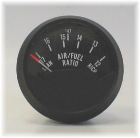
I have had a Westac analog air fuel ratio (A/F) gauge installed just above a vacuum gauge in my coach (77 Kingsley) for at least six years. Its range is from 17 (Lean) to 12 (Rich) with 17 on the left.
The A/F gauge is used to monitor the operation of the fuel induction system. In my case this is the original carburetor. The ideal ratio is 14.7, and the gauge has this ratio marked, but it is seldom seen. A vacuum gauge enhances the use of the A/F gauge.
During normal operation the power valve in the carburetor enriches the fuel / air ratio between 6-8" of vacuum. In my case, this occurs at 7". As I drive with a light load on the engine (Above 7" vacuum) the A/F gauge needle will be all the way left (17). As I begin to ascend a hill, or increase speed, the engine load increases and the vacuum decreases. When the vacuum drops below 7", the power valve goes rich and the A/F gauge needle will go all the way to the right (12) and stay there until the vacuum rises enough to deactivate the power valve.
In my case, when the vacuum dropped below 7", the needle would go full rich, as it should. But, after short time at low vacuum, the needle would slowly move over to full lean. This indicates the carburetor is not working properly (Not supplying enough gas to the secondaries). After long hills, the needle would stay lean and not respond to vacuum changes for a few minutes after cresting the hill. I checked the carburetor and it was okay. My next thought was that the O2 sensor (Which drives the A/F Gauge) was getting too hot and not generating the voltage necessary to drive the A/F Gauge. I replaced the O2 sensor and the symptoms stayed the same. Later an expert in engine emissions said it was not possible to get an O2 sensor too hot.
Not too long ago, I read an article by Wes Caughlin discussing intake manifold cracking problems. So I removed the carburetor and sure enough, there was a little crack between the secondaries. Next I removed the intake manifold and took it to a machine shop. Their equipment revealed extensive cracking in the area under the carburetor. This intake manifold was now a paperweight!
When a heavy load was applied to the engine, the exhaust would get
hot,
the cracks between the intake area and the exhaust area would get
bigger
allowing more exhaust to dilute the intake charge, leaning out the
mixture,
which the A/F Gauge reported.
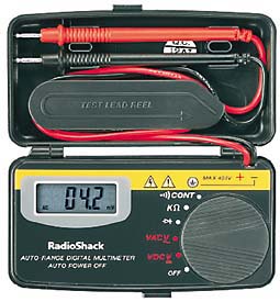
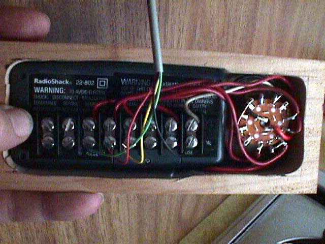
This
is the Radio Shack 22-802 DMM.
ISOLATION
When you use a hand-held meter, the isolation is excellent because
the power for the meter is from batteries. This is critical
because
as you will see in the battery charge analyzer application you cannot
connect
the measurement ground to the power / chassis ground. Many of the
digital "round" meters and the flat panel meters do not have good
isolation
between the power supply ground and the measurement ground.
To get accurate, noise free, and safe measurements, a battery powered
digital
meter is the easy way.
 This
flat digital meter is fabricated from a Radio Shack # 22-802 Digital
Mulitmeter.
This meter was chosen because of the following features:
This
flat digital meter is fabricated from a Radio Shack # 22-802 Digital
Mulitmeter.
This meter was chosen because of the following features:
Three and one half digits
Auto Ranging
Self Turnoff
Very Small and flat
Inexpensive
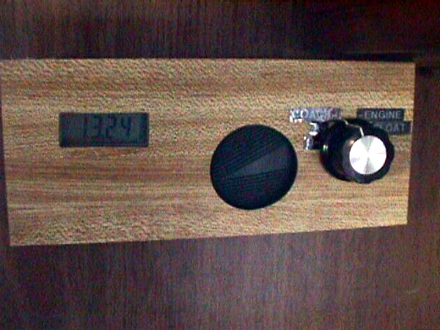
 A
donut of wood is cut so that the voltmeter will slip inside and a small
window is cut in the Formica cover on the front of the
donut.
The advantage of this fabrication is that it is possible to select any
color for the front of the final meter. The wood grain shown here
is not the final color, I like black like the original GMC monitor
panels.
A
donut of wood is cut so that the voltmeter will slip inside and a small
window is cut in the Formica cover on the front of the
donut.
The advantage of this fabrication is that it is possible to select any
color for the front of the final meter. The wood grain shown here
is not the final color, I like black like the original GMC monitor
panels.
The rotary switch is a two pole six position switch that selects the
voltages to be measured.
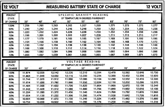
Read this background information about batteries and chargers to help understand this Monitor.
BATTERIES--AND OTHER ELECTRIC STUFF
Now that you understand batteries and chargers, you need a way to measure the charge remaining on your batteries. The table below shows the two ways to measure the state of your battery. Not many of us are going to measure the specific gravity of the acid in the battery, so that leaves measuring the voltage. To effectively measure the voltage in this application, you have to measure the voltage to at least .01 volts which is a 3.5 digit voltmeter. The dash and OEM voltmeters in the GMC are not accurate enough to do this function. In fact, most of the digital battery monitors only measure .1 volts which is not accurate enough.
The second table shows the voltage of two Trojan 6 volt batteries connected in series to provide 12 volts. The table shows what voltage you should expect to read at different temperatures and charge levels. Using the Multi-point Temperature Monitor and the Digital Voltmeter described earlier, you should be able to accurately determine the charge of your batteries. For example if the temperature of your battery is 60 degrees fahrenheit, and your battery voltage is 12.39 volts your battery is fully charged. However, if your voltage is 11.76 volts your battery is only 50 % charged and it is time to charge up.