Installation Instructions
DP-103 & DP-104
Installation
Instructions
Congratulations
on your purchase of the high-tech DIGI-PANEL.
It was developed to provide many years of highly reliable service and
provide accurate and fast measurements of many functions, visual and audible
alarms when troubles occur, plus an optional ENGINE
KILL (automatic shutdown) feature. Some of the more common applications are
trucks, commercial and light duty, motor homes, automobiles, construction and
other miscellaneous equipment.
Installation
can be accomplished easily by anyone with basic skills and knowledge. No special
tools are required; some drilling may be necessary to mount the hanger bracket.
The
kit includes:
(1) DIGI-PANEL with its wiring harness including temperature
sensors.
(1)
Mounting bracket.
(1) Oil pressure sender.
The
temperature
sensors are connected to the ends of the twisted pairs of wires; care should
be used to not severely jerk on the sensors/ wires.
The
first thing to be determined by the installer is the preferred mounting location
of the panel. The most common sites are on top of the dash or just below the
dash. Overhead locations are sometimes selected. For overhead mounting, verify
that you have purchased a unit with the "extended harness" option,
which provides 4' longer leads.
To
mount below the dash, use the hanger bracket provided. Holes may already exist
in the bottom of the dash; if not, drill holes at the desired locations. For
mounting on top of the dash, the panel may be mounted with or without the hanger
bracket and by drilling or using double-sided or velcro tape.
Once
the panel location has been determined, the oil pressure sender should be
mounted on the engine. The sender is the iridite coated cylindrical can which
has a 1/4" terminal on one end and a 1/8"-27 NPT fitting on
the other end. If an existing gauge or warning light exists, it is best to
keep that operational (the computers on newer rigs require that the factory's
sender be operational). It can be
accomplished by removing the existing sender or switch temporarily, installing a
steel or brass nipple and "T" and reinstalling the sender or switch. Most
vehicles have either a 1/8" or 1/4" NPT fitting. If it is 1/4",
use 1/4" nipple and "T" and then use a 1/4" to 1/8"
reducer bushing for the new sender. If only the new sender will be used and the
vehicle is 1/4", only a reducer bushing is required. These fittings are
available from most quality hardware or auto parts stores. If the
location of the oil pressure sender or switch cannot be located, the parts
counter of the vehicle manufacturer has diagrams showing their location.
Prior
to routing the wiring, it is best to check under the dash to locate a hole
proving access to the engine compartment. There are normally large rubber
grommets where existing wiring harnesses are routed. Most front wheel drive
vehicles also have large seals where the articulated steering column routes
through the firewall. Care must be exercised that the wires remain clear of the
steering column itself if this routing is used.
Connect the wires in the harness as
follows:
Caution:
High temperature wire is used for the
DIGI-PANEL, however as is normal in all motorized applications, wires
must be kept clear of hot exhaust manifolds and pipes, etc. Also, keep wires
away from spark plug wires as much as possible. Do not run parallel to spark
plug wires, but cross them at a sharp angle.
RED (Power/ +12Volts):
This
is easiest to connect to, or near, the fuse block. Use a circuit which is
powered only when the ignition switch is in
either the ON or ON and ACCESSORY position. The more common lines powered
in the ON position are the fuel pump (if electric), ignition control, and
windshield wipers. ACCESSORY lines include the radio. Power windows may be
either.
BLACK (Ground):
Normally
best to connect directly to the engine on the alternator mount, valve cover or
miscellaneous bracket. Grounding to
the dash may be attempted if the vehicle has a good engine/ body
ground. This can be verified by noting a change in the oil pressure
"zero" reading when the ignition is turned on, the engine not running,
and then turning on the headlights or turn signals. If the reading changes under
those conditions, it indicates a poor engine/ body ground. (This also causes
reduced brightness on the vehicles headlights at night.)
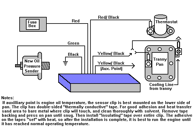
GREEN (Oil pressure):
This
connects to the previously installed oil sender unit on the engine.
RED/ BLACK TWISTED PAIR (Engine
temperature):
This
has a temperature sensor attached and mounted to a copper clip with a 3/8"
hole. The best mounting location is one of the thermostat housing bolts. It can
also be mounted on an intake manifold bolt, preferably next to a coolant
passage, if it is a water cooled engine.
YELLOW/ BLACK TWISTED PAIR
(Transmission and/or Auxiliary temperature):
(Also see notes below)
This
will also have a temperature sensor mounted on a copper clip. It can be attached
to the transmission cooling line by "curling" the clip and clamping
with an adjustable heater hose clamp. The alternate method is to attach to a
transmission pan bolt; best to select a bolt close to the center of the
transmission body. It is best to place a flat washer between the bolt head and
temperature copper clip to prevent damage to the clip.
ENGINE KILL equipped panel: This panel includes three additional
wires coming from a heavy duty relay inside the DIGI-PANEL
WHITE: Common (W.- Relay Wiper)
GRAY: Normally Closed
(N.C.)
BLUE: Normally Open (N.O.)
Two
engine shut-off, or kill, modes are available. First is opening up a circuit,
such as the ignition hot wire to the coil or ignition computer, when an alarm
condition occurs. For this, cut the hot lead and connect the WHITE and GRAY
leads to the ends. To complete a circuit, such as to energize a fuel
cutoff solonoid, cut that wire and connect to the WHITE and BLUE leads. When
installing a new solonoid for this purpose, connect BLUE
to the solonoid and WHITE to the battery.
When
installation is complete, turn on the ignition. The BATTERY VOLTAGE gauge should
light up the right yellow element (3rd from left) if the battery is fully
charged at 12.6V. The OIL PRESSURE gauge
should light the the left-most red element which is zero pressure. Sometimes,
due to ground resistance, either no light or a light to the right of zero will
light. Remove the 4 screws holding the lid and adjust the blue control directly
behind the oil pressure gauge for proper zero. DO NOT adjust the
other controls; they are factory calibrated for correct readings.