REAR SUSPENSION
[mobile alignment]
SOJOURNER
The newest six wheel bogie vehicle since the GMC. They know how
to cut the bumps in half.
[TORSON TOOL] [HEIGHT ADJUST]
[GREASERS]
[BOGIE PINS]
[AIR BAGS] [VALVE CONNECTORS]
[REMOVING BAG] [ALIGNMENT
SETTINGS] [REAR
BEARINGS] [EXTENDERS AND 4
BAGGERS]
[NEW AIR BAG INSTALL][CONES] [BAG
SUB] [RAISING ON JACKS] [AIRBAG
AGE] [BOGIE BENDERS]
REAR SPINDLE NUTS
The Maintenance manual is very mis-leading on how to tighten the rear
spindle nut. The 25 ft-lbs is only the initial torque to seat the
bearing & then it is to be loosen & re-torqued to finger tight
or
less. Over torque of the spindle nut will lead to a very hot
bearing
very quickly. I have seen the spindle shear off on several
coaches
that were torqued to the 25 ft-lbs level & left there (the wheel
passed
the coach as it slowed down). Big $$$$$$ repair.Duane
But here's the exact instruction from X-7525:
"and hubs on spindle. Tighten castilated nut (figure 17) to 25-30 ft .
lbs., back nut off one half turn and then finger tighten until cotter
pin can be installed."
Assuming the spindle threads are 16 tpi, that's
1/2*1/16-1/6*1/16=0.021" axial clearance (plus whatever slop comes from
grease interference, etc.);
I'd rather see <0.010" -- and even less with my disc brakes.
Many references I've seen recommend 0.001"-0.005", but I think anything
<0.005"
is risky.JMHOKen Henderson
What about rear bearings and seals?
Checker had all the parts in stock and were cheaper than AutoZone.
They carried Chicago Rawhide (CR) which is an old line US manufacturer.
When you look closely at the
inside bearings you see
"Mexico" on them!! The outside bearings are made in Germany. The
outside cones and seals made in USA.
REAR SEAL
The seals are Part No. 21771 and costs $3.89 each. (there is only
one
per wheel and it is on the rear)
Rear---National# 8974S, C/R# 21771Denny Allen
SEAL UPDATE (10/5/10)
Dave Lenzi found some are wrong and even if you have the correct
part number on the Timken seal you have a big chance it won't fit
right. They have two different seals using the same number.
The grease will leak out and there goes the bearing..GeneD
I think the jury's still out on the final verdict. But for
now, the surest check seems to be the 0.260" measurement Rob quoted
from Dave. That's the distance from the inner rim (the "sharp
one") to the lip of the flexible seal. In other words, perhaps
easier to remember, 1/2 through the axial dimension of the metal seal,
which is 0.500" KenH
Dave Lenzi gave me two manufacturers for the rear wheel seals that
are OK.
They are: Chicago Rawhide-3857731 and SKF-21771.
http://www.gmcmhphotos.com/photos/showphoto.php?photo=36356&title=says-made-in-the-usa&cat=5621
I picked up one SKF from NAPA today and it is the correct seal..
GeneD
REAR BEARINGS
The inner cone (cup) is LM501310 , $3.89.
The inner bearing is LM501349 , $8.29.
The outer cone is BR15243, don't remember the cost.
The outer bearing is 15103-S, don't remember the cost. Emery Stora
REAR LEVELING VALVE CONNECTORS
PICTURES
http://www.gmcmhphotos.com/photos/showgallery.php?cat=3101
Modifying the bellows port adapter fitting on the
ride height valve to accept compression fittings when the plastic
fittings go bad. Well I got mine finished and
it works. I will try to explain. Some of what I think I have found out
is that the early
valve
connections were metal as shown in the maintenance manual. Page 4-21
of manual attached. No where in the parts or
maintenance manual have I found any pictures of the plastic connectors
that I have had trouble with leaking and have not
found any replacements available to repair. It is my understanding that
GM started putting the plastic connectors on the coaches in 1975 and
that when they star leaking there is no replacement available for the
Bellows port unless you buy a new leveling valve. We are not the first
to have problems with the plastic valves. We may be the first to fix
them with 3/8 to 1/4 compression fittings.
Parts required.
(2) 3/8 compression ferrule
sleeves
(2) 3/8 compression nuts
2 inches of 3/8 copper
tubing.
(1) 3/8 to 1/4
reduction compression fitting.
(1) little sleeve that goes
inside the 1/4 inch tubing
The first thing I did was remove the bellows
port adapter assembly from the body of the height control valve.
It did not take much effort to break it loose. I had clamped the
mounting bracket in a vise and used a medium crescent wrench to unscrew
it. Once I had broken it loose I unscrewed it by hand. I caution you to
be careful and not loose the screen. After removing the adapter I took
it to a machine shop and machined the
end where the plastic fitting attached. I machined the inside to match
a
3/8 female flair fitting. All I had to do was put it in a lath and
drill and ream the port end. I did not drill it quite as deep as a
standard fitting. I tried to not go any deeper than the existing
depth of the 1/4
inch hole that was there for the plastic
fitting. After drilling and reaming the 3/8 diameter I took a 90 degree
counter sink and put a very light chamfer on the front edge for the
flair fitting that slides on the tube to seat against. This completed
the required repair of the adapter fitting. The compression nut that is
going to screw on the adapter fitting needs to be machined so that it
will not bottom out on the shoulder
of the adapter fitting. The nut I had was .470 long . I machined
.070 off of the threaded end. If you don't do this the compression nut
will bottom out on the shoulder before the flair is compressed enough
to
tighten down on the tubing. One of the attached pictures shows the
different
lengths of the 3/8 compression nuts. This completes all of the
machining
required for this modification. The rest is just assembly.
Install the adapter assembly in the valve body.
Attach the 3/8 copper tube to the adapter assembly using the modified
compression nut. Then to the other end of the copper tube attach the
3/8 to 1/4 reduction compression fitting. When you attach the 1/4 inch
air line to this fitting be sure and install the little sleeve inside
the tube to aid in sealing. This fitting leaked air until I installed
the sleeve. Andy you said, "I need two as I
broke both yellow and red". On my system the fitting that the red line
goes into will take a1/8 pipe thread. You can buy a 1/8 pipe thread to
1/4 compression fitting that you can screw right into the air inlet
port fitting. This fitting does not require all the modification the
bellows port does. See all the pictures attached. Charles Wersal
----------------
I believe this is the adapter you are looking for. I had
to replace mine on my '76 PB. It was on top of the three way
valves
in our valve cluster. I was able to purchase them from a local
Parker/Skinner distributor. About $10 ea.! It took a lot of
effort to find this part because the part number on the valve is not
used. I ended up sending them a picture of the valve to get them
to believe it was one of their valves.
After all my effort in finding a source I found that CINNABAR has
the adapters
in stainless steel. Learned from reviewing old publications of
their's.Below
is a copy of part of my email from Parker.
>The adapter used on this valve is a 1/8 PTF x 1/2 UNF. Our
P/N is J21-001.
>This item is not normally sold individually, but we I spoke with
our
>customer service manager and we will allow a one time purchase on
this
>item. Please contact your local distributor at
www.parker.com/skinner
>under distributors for P&D if you wish to purchase this item
from us.
>Or, if you prefer, you have the basic info on the adapter and can
source it
>elsewhere.The valve you have is an old valve we manufactured for
GM.
Todd Elson
Air Bag Extenders and Four Baggers
There is a new article in the Cinnabar GMC news (Dec98) that says:
 Picture
by Mike Finnicum
Picture
by Mike Finnicum
Air bag extenders:
makes the ride
softer but increases the wallow side-to-side
do not extend bag life
An earlier article in Cinnagbar News Sept. 98 , vol 17 , talks
about four baggers.
Four baggers:
stiffen the ride
(reduce the wallow)
eliminate the
preferred bogie action
reduce the leveling
action
raise the pressure
required
increase the bending
load on the center arm
Owners love all of these for different reasons. Be sure to
read the
literature to make your own decision .gene
-------------
I installed the four-air bag system during the GMCMI
Myrtle Beach Rally in March 1995 at the same time as I installed
Leigh's six-wheel disc brake system. As I said the other day in
response to an e-mail message asking about the wear of carbon metallic
brake pads, I have over 40,000 miles experience with the system.
Compared to the original,
I notice a definite increase in the fore-to-aft dampening of the ride,
and
much greater stability in truck-rutted asphalt paving. I can't
even
feel the difference when the coach drifts over the joint between the
roadway
and paved shoulders, and have demonstrated such with folded arms not
even
holding onto the steering wheel at the time. When I drift onto an
unpaved
shoulder, there is no problem recovering. I haven't met anyone
yet,
without Leigh's system, who feels very comfortable in running off the
edge
of the road.
Leigh also claims that the rear-rear axel spring rate is doubled to
around 815 psi, compared to the original. This in turn, makes the
brakes
on the axle able to exert more stopping ability prior to lock-up (which
I've never experienced thus far).
If you already haven't heard it in a few previous e-mail messages,
the original air bags are rumored soon to be in short supply, as the
molds used to make them are supposedly near the end of their
life. Then what
are you going to do??????
I would encourage any doubting Thomas's to go with Leigh during the
GMCMI rally's, when he routinely takes people for a demonstration
ride.
You can't believe the stability his coach demonstrates.
Paul
--------------
My "light weight" 23' tips the scales at 5800 lbs on the rear axle with
all tanks empty. I'm guessing the left tandems carry about 3200 of that
(genset and kitchen on that side).That's 1600 lbs per left rear tire
with O.E. suspension, which distributes the weight more or less equally
within each tandem. But it looked to me that the 4-bag conversion would
result in the momentary
transfer of the entire weight on one side back and forth between the
tires
in that tandem, and our load range E tires are rated to only 2680
lbs.Richard
---------------
PREVENTIVE MAINTENANCE
REAR
SPINDLE / HUB RECALL
> There are no time
limits on the recall. Larger pins were introduced at
TZE0X4V101024 and coaches earlier than this Vin number are subject to
recall.
It should be noted, however, that the
recall is for rear hubs and spindles, not bogie arms. My spindles and
hubs were replaced as part of the recall, but I still have 1-1/4" bogie
pins. Rick
----------------
The Recall is 74-C-07 and is dated May, 1974.It covers all 1973 and
1974 GMC Motor Homes shipped prior to May 1,1974.
It states that "the rear suspension outer wheel bearings may fail
and a
rear wheel coul separate from the vehicle and cause property damage or
personal
injury."The recall would replace all four rear spindles, all 4 brake
assemblies,
hub and drum assemblies, inner bearings, outer cone and roller
assemblies,
washers, nuts, cotter pins, inner and outer dust caps, etc.
In the Recall it states:
"Dealers are to service all vehicles subject to this campaign
regardless of the mileage, age of vehicle, or owner."And, as I said in
an earlier message, there is no time limits on recalls mandated under
the National Traffic
and Motor VehicleSafety Act.-EMERY
------------------
Not to belabor what is probably an old topic to many owners, but rather
for the benefit of new owners or subscribers, I just had a nice chat
with Wes Caughlan and he outlined the basics of what to look for in
terms of whether or not this recall has been done on a coach.
He indicated that even if the S/N records show it as having been
done, the records could be wrong. The four things he said to check that
will be about 99% positive from easy to difficult are:
1. The wheel centering protrusion on the hub should have eight
rather than
four notches.
------
 I talked to Ivan at Cinabarr to find out how
to see if
mine had been done I sent the photo to Toby to help him. The easy
way to tell if it has been done is to remove the hubcap and look at the
shoulder that the
wheel centers on. If it has 4 notches equally space around this
shoulder it has not been replaced. If there are 8 notches around this
shoulder it has been replaced or is the later release. I got this info
direct from Ivan
at Cinnabar. I am attaching a picture to help clarify sholder notch.
Charles
I talked to Ivan at Cinabarr to find out how
to see if
mine had been done I sent the photo to Toby to help him. The easy
way to tell if it has been done is to remove the hubcap and look at the
shoulder that the
wheel centers on. If it has 4 notches equally space around this
shoulder it has not been replaced. If there are 8 notches around this
shoulder it has been replaced or is the later release. I got this info
direct from Ivan
at Cinnabar. I am attaching a picture to help clarify sholder notch.
Charles
--------------
2. The inner dust cover (not the outer decorative cover, just before
you get to the axle/bearing nut) should be 2-1/2" in diameter.
3. The axle/bearing nut should be 1-1/4" rather than the original
1-1/16" (can be measured with a socket).
4. The spindle and backing plate hole should be 2-1/4" rather than
the 1-7/8" of the original.
And in case anybody else is interested, the full set of service
bulletins, all back issues of the GMC Motorhome News, and a year's
subscription will set you back $154.00 plus shipping. At today's prices
here in Redlands of $2.259 for gas, it's about one round trip to Las
Vegas. I believe it to be money well spent.Carry on!Toby Maki
BOGIE PINS
Another variable from coach to coach is the wear on the rear pins. I
have a coach here that had a mind of its own according to the owner.
The rear pins were very loose so the coach was riding on four casters
back there. The easiest/best way to check and get a repeatable
measurement is: Support
the coach under the rear suspension mounting bracket at approximatly
the
correct ride height. Loosen all lug nuts on both wheels. Release all
air
from the air bag. Jack up the suspension arm only--just enough to get
the
wheel off.
With a piece of wood, standing on end, support the end of the control
arm at the spindle end. Move the spindle end of the arm towards and
away from the frame and measure the total movement with a tape measure.
GM Service Bulletin #75-TM-4 states 1/8" is maximum.
A big job to fix but this coach was about 1/2" movement on three of
the four wheels. I had to bush the inboard end of the bracket, replace
pins, bushings and top hats. Denny
------------
BOGIE PINS should be greased about every 1000 miles
or every trip. They should be greased with the weight off of the
bogie as
described above. Raise the unloaded wheels with a shovel or pick
to remove the weight off of the pin while applying the grease.
Build Your
Own Dual Zerk Bogie
Greasers
A tool has been made that will make sure the grease gets to the rear
of the bogie pins. Click on this URL.
http://www.gmcmhphotos.com/photos/showgallery.php?cat=3576
You can buy these already made. Look here to find the vendors,
use
(Ctrl-F) to search for Bogie
Also sold by Jim Kanomata and Jim bounds
http://www.bdub.net/GMCSupplierLinks.html
They are also listed on Ebay. Go to:
http://www.ebay.com/
then search for "Bogie easy" and you will find the listing
HOW DO I INSTALL THE GREASERS
The bogey pin is a tube with a zerk threaded into the end cover.
Ithas two holes in it, an inboard hole close to the frame rail and an
outboard hole, both designed to inject grease in the two bushings
oneach pin. If you use the single factory zerk, the grease tends to
smoosh out one end, taking the path of least resistance, and not getto
the bushing at the other end.
There are two possible solutions to that problem. The first is to
movethe bogey around while you are injecting grease such that you work
the grease into both ends. That's what you use the shovel for. Jack up
the bogey frame, let the air out of the suspension, and then use a
shovel as a lifting tool under the tire. Move the tire around until you
canget the grease to smoosh out both inboard and outboard ends of the
bogey pin bushings.
The better solution is to remove the zerk and replace it with a
bogey greaser. The greaser that uses two zerks is the improvement. The
way
it goes together, one zerk will inject grease right under the
fitting, and the other zerk will inject grease out the end of the tube.
The flare or collar on the end of the tube keeps the two separate. That
way, one zerk will force the grease out one grease hole, and the
otherzerk will force grease out the other hole. That keeps you from
needing to jack it up and take the weight off the tire.
Those of us who have '73 coaches with the original pins can't use
this trick, though. Our grease holes only go halfway through the pin to
a
single hole in the middle. (I didn't find this out until I'd
installed greasers, and I kept wondering why I was having to shorten
the tubes!)
Rather than jack up the back of my coach, I just put my wood
blocks under the bogey frames that I use for winter storage, let the
air out
of the bages, and then I can wiggle the tires back and forth even
without a shovel. A 4x6 timber, standing with the tall dimension
vertial, will keep the coach high enough for storage.
Denney
AIR BAGS
SCHRADER VALVES -
Carry these for emergencies, and this is what they look like ,
and where to find them
http://www.gmcmhphotos.com/photos/showphoto.php?photo=26938&title=slide111&cat=5047
HOW TO INSTALL A
NEW AIRBAG
Here is a photo explanation
http://www.gmcmhphotos.com/photos/showphoto.php?photo=18215
I would not have believed it if I
had not seen it with my own eyes. I did have one bag that
scared me a bit and we let the air back out and made sure the coach was
high enough. You have to have the wheels able to go all the
way down. The more room the bag has the better it can assume its
shape.
--George
***************
When I did my air bags several
years ago, I put the cones on and fitted a Shrader valve on the end of
the bag. I put one end on the ground and started adding air
slowly while pushing down. The cones came in against the bag just
the way they were on the coach. Just don't put any extra air in
or they will pop out again. Doesn't seem possible, but it works.Gene
Dotson
AIRBAG /
AIRSPRING CONDITION OR AGE DETERMINATION
Since it is not possible to determine the condition of the
airbag by looking at the rubber covering:
see the discussion below
you might want to use the age-of-the-bag, to make your decision to
replace the airbag. I determined to post the Firestone info
on this so we don't loose it again, and again, and again. ( thanks to
harperJ for finding the link again in 2005;<)
http://www.gmcmhphotos.com/photos/showphoto.php?photo=25912
You might also want to read the condition information from the
horses mouth (does this date me ?),Firestone. This is
better than information from the other end of the horse ;>)
http://www.gmcmhphotos.com/photos/showphoto.php?photo=25911
Looks like this info also applies to 4 baggers
as always, there is no definite cutoff date or criteria for this
maintenance operation. good luck gene
SHUTOFF VALVES DANGER
I know of 3 separate failures this year, of the short nipple that goes
between the cutoff valve and the air bag. The nipple used by most
of these assemblies is brass. This would seem to be the quality
thing
to use here since it will not rust or corrode. However the
combination of assembly weight, lots of motion and thin material in the
nipple leads
to the cracking of this nipple.
http://www.chaparral-co.com/valves.html
The answer to this problem is to replace the nipple with a steel
(stainless for Manny) nipple. It appears prudent to replace the
nipple NOW before it breaks at an inopportune time and location.
One of the stricken owners was looking for an air leak, when the nipple
broke and the assembly shot into the wheel well, leaving a very short
piece for extraction in the Air Bag. He was very glad his head
was not in the wheel well when this exploded.....
Always put jacks, blocks, jack stands, (everything you can find)
under the frame and bogies of the GMC when ever you work on the rear of
the GMC, and I release the air pressure to the bags. There is a
8,000 lb weight and a 120 lb pressure vessel in there, that could fall
at any time , and we all know a GMC gets lower than a Snake's belly
when it falls....... Yikes gene
AIR BAGS - O - RINGS AND STAINLESS NUTS
THE O RINGS
A while back, I asked if anyone knew the correct size for the "O" ring
used to seal the adapter piece to the air bag and didn't get a
response. After trying serveral sizes, it appears the correct "O"
ring has a 7/8" ID, a 1 1/16" OD and a 3/32" diameter.Jim Moore
*******************************************
Yes, the fitting that the air line is connected to is threaded into
another fitting that takes the mounting nut. If you "double nut"
that thread with 2 nuts and back it out of the air bag itself, you will
find dwn in the "female" hole a shoulde that has a rubber "O" ring on
it. Admittedly, Firestone said they installed the fitting dry
with an air tool which sometimes tears the seal. Take it out and
inspect it. If it is deformed or torn, take it to your local
hardware store and get a replacemnt. We put just a light film of
RTV on the seal to act as a lubricant as the fitting seats home then
when t cures I think it will help to seal everything. This is a
common problem if you have a leak and cannot find it anywhere.,Jim
Bounds
***************************
THE NUTS
Mc Master is king--
folllowing a link from Bob Burkitt, to John shotwell, here are
the Mc Master numbers for the
stainless air bag nuts
98438A036 1 Pack 410
Stainless Stl External-tooth Lock Washer, 3/4" Screw Sz, .768" Id,
1.26" Od, .047" Min Thickness
91847A555 1 Pack 18-8
Stainless Steel Hex Thin (jam) Nut, 3/4"-16 Screw Size, 1-1/8" Width,
27/64" Height
John Shotwell
AIR BAGS - NEW
Air bag price $219.00 This price sheet does not
list alum cones.
Gateway Motor Home Co. High Ridge,Mo
Questions 1-636-677-2277
Order line 1-800-654-0374
AIR BAG TESTING
A number of years ago Wes Caughlan reported to a GMC Western State
Roundup, that one should never install an Air Bag w/o first testing it
for air leaks. He stated that 35 % of new airbags from a
warehouse (about 1990) was tested & 35% had leaks. Warranty
is for only 90 days & should be
tested as soon as received & before installation. The way to
test
an air bag is to install a schrader valve (1/4" pipe thread) into the
end
using "Pipe Sealant w/Teflon" & then pump the bag up to 40 PSI
&
submerge it under water to find leaks. Works For MeDuane Simmons
HOT DOG AIR BAGS can be prevented by rotating the bag
180 degrees (top to bottom) once a year. This also keeps the
threads
clean so the bag is easily replaced in case of failure. The air
bags
tend to take a set in the inflated condition so it is also helpful to
rest
the coach on a block between the wheels and let the air out of the bags
when the coach is in storage.
TREATING THE BAGS with brake fluid or rubber
treatments is
not recommended. Cracking of the outside rubber does not indicate
a
bad bag. There does not seem to be a good indicator of a tired
bag. gene
Does everyone know that the GMC airbags were originally made to
serve as
supports for laboratory benches so as to prevent vibrations? GM
adapted
them for the motorhome. Their construction is actually a fabric
bag
that has a rubber coating. The coating does check (just like
tires exposed to the sun and weather). I suppose you could use a
rubber
preservative or coating but be careful that you don't use one that will
deteriorate the rubber. (No petroleum based substances). Also be
sure
you do not leave a sticky residue as that would trap sand particles
where
the bags fold on the cones and possible leaks will result. There
are
some tire dressings that contain polyglycols that won't harm
rubber.
I don't use a coating. I do, from time to time, inflate the bags
all
the way and then scrub them well with a brush and car wash soap to get
off
the road oil and dirt. The fender skirt ("T" or triangle or the
full
flare skirts) shades the air bags. If you don't have them you
should
consider putting them on. Emery
Put a Shraeder valve into the bag and inflate it with shop air or
whatever. Put the coach weight on it. Now the bag
won't turn as you remove the
nut. Once the nut is off, deflate and carry on.
Shraeder valves are readily available at auto or hardware stores.
Usually called tank valves. You want 1/4" pipe thread so a 1/8"
to 1/4" bushing
may also be needed.Denny Allen
SCHRAEDER VALVES - AND WHERE TO GET THEM
http://www.gmcmhphotos.com/photos/showphoto.php?photo=26938&title=slide111&cat=5047
CONES
- ALUMINUM
VS PLASTIC
Firestone recommends the plastic cones be used only if their entire
base is supported. The GMC only supports the center of the
cone.
Aluminum cones can be used either way. The two types of cones are
interchangeable using the same bag.
There have been reports of the plastic cone disintegrating resulting
in damage to nearby objects, so far, the objects have been
inanimate. I would be very concerned about putting my face close
to the plastic cones when the bag is under pressure.
Here is an example:
"""""
I can attest to the exploding plastic cones. When mine came apart I
found pieces all the way up on the shop roof. I'd had my face in that
wheel well just seconds before. So I could have been hurt if the timing
had been just a little different.
These exploding cones may well be isolated instances but then so is
getting struck by lightning.So be aware and be careful Dave Mumert
********
I read in an old Cinnabar newsletter that there are black and gray
plastic cones. The black ones are the ones that break, according to
Wes. Kelvin
*******
Several years ago, I had my 77PB in to Buskirk's for rear wheel
alignment. Clarence noticed I had plastic cones and changed them
to aluminum
without charge.Said the plastic were not dependable or safe. That was
good
enough advice for me to recommend changing all plastic cones to
aluminum.
Just my opinion.Andy
*******
The plastic cones are typically black in color and if you tap them
lightly when they are out make very little sound. The early alum
cones are not painted, the later cones are power coated in black.
Both of these cones make a nice ringing sound when tapped with a hammer
if you hang them from a string. J.R. Wright
*******
The plastic cones are very dangerous & should be replaced with the
Aluminum cones. Yes I have seen the Plastic cones let go/blow
apart & do not want to be around when it happens again. The
Aluminum Cones can be Identified by having radial
supports/ribs extending from the center of the cone to the outer
surface of the cone as viewed into the end of the cone while installed
in the bag. Beware when replacing the cones, there are two
different configurations. One cone has a large hole in it (air
filling end) & the other cone has a small hole for the non filling
end.....don't cross then up. Duane
Emergency
Air Bag substitute
This Rod is used to replace a leaking air bag in an emergency to get
you home or to a repair location. To insert the rod the GMC must
be jacked up and the old air bag removed. This rod is then
inserted
in place of the air pag to keep the rear suspension level. With
this
rod installed, there is no suspension for this set of wheels, so the
driver
should drive carefully and not drive any farther than necessary to
replace
the bad air bag.
The BagRod is made up from a 3/4 inch threaded rod with a 3/4inch
pipe over it and two washers.
http://www.gmcmhphotos.com/photos/showphoto.php?photo=3566
The dimensions are :
3/4 inch Threaded Rod 18 inches long
two 3/4 inch nuts
3/4 inch gal. pipe 15 inches long.
two each 2 inch washers
Gene.
GMC International News Letter # 18
A 4"X 4" piece of wood cut to the length of 13.5" with a hole in the
center
of each end to accept a 5/8" X 5" lag bolt has been used.
A 1 1/2" iron pipe 13.5" long and used a 5/8" threaded rod 16" long
with a
nut and lock washer at each end.
GMC Newsletter # 37
A 3/4" threaded rod 18 1/4" long and 2 nuts threaded onto each end
of the
rod. Distance between bogie arms 13.5"
Ragusa sells a temporary replacement airbag rod, complete with
rubber pads
and hardware for $38.00.(RV-08)
http://www.ragusarv.addr.com/
Peter
----------------------------------
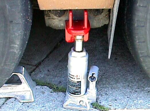
RAISING
THE GMC ON
JACKS, HOOKS, RAMPS N STUFF
Raising the GMC on jacks is problematical:
The frame often gets bent
The Jacks slip
The fame gets twisted
You need a really big jack
It is really not very safe under a GMC on jack
stands
It is almost impossible on dirt or gravel.
TON
JACK STANDS - YOU CAN MAKE -Steve
Stacked Blocks Ramps and
front ramps
Plans
for Ramps
Hooks,
Ramps N Stuff
Jack
Pad for the GMC Front
The best way to work on the bottom of the GMC for us PWOP's . (
People With Out Pits) is to build ramps of stacked 2 X 8 boards.
Mine are 4 high which will raise the GMC something less than 8
inches which with the 4 inches the air bags will raise,
allows you to get under the rig safely. You can then place
the jack stands under the frame for added safety and use the old
reliable 6 inch by 8 inch block under the bogie support.
Using this method you can :
Drain the gas tanks ( raise the driver side)
Drop the gas tanks for hose replacement
Repair the Black tank
Replace the Iso pads on the frame
Add the booster electric fuel pump.
Drop the radiator for recoreing
Add the Macerator poop pump
etc, etc
Lots of good stuff to do under the GMC for us pit-less
folks.
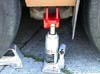
THE HOOK-N-PLATE JACK
It has come to my attention that not all of us have a Hook so that we
can use a small bottle jack to raise the rear end of our GMC coaches
without removing the T divider. The shop manual says to use
a one inch board to raise both bogies and one GMCer uses a spring
leaf. Florence Or. was not progressive enough for me to find a
spring leaf the correct
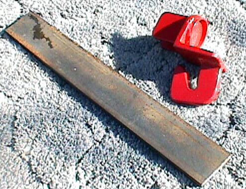
size so I used a steel plate.
----------
Several years ago when I bought a new screen door from Alex Birch he
sent me several drawings of improvements I could make on the GMC.One
was
a bar to go under the bogies 11 X 3 X 1/4 inches flat bar stock.I made
a couple, but I didn't like them because they would bend.That's when I
came up with the idea of a spring leaf(68 Toro) and it works great.The
arms with 1 1/4 pins are closer to the bogie than the 1 1/2 pins so I
used
a section of a spring leaf close to the eye where it's tapered.The
longer
you make them the harder they are to put in and 11 inches is long
enough.HTH
Milt
------------
 There
are at least four sources for the
Hook.
There
are at least four sources for the
Hook.
--------------------------
Here are some links to hooks (1/30/08)
http://gmcwsproducts.blogspot.com/2006/04/jack-hooks.html
-----------------------
Paul Z. Bennett, 2400 Blossom St., Columbia SC 29205, Phone:
803-799-4323. Email: bennettpz@aol.com.
----------------------
Wayne Alumbaugh, has a stepped hook for flat tires.
http://www.bdub.net/alumbaugh/
 -----------------------
---------------------
I like the one shown (Bebe)since there is a lip around the area
where the
jack shaft makes contact. This lip will help keep the jack from
slipping.
The Hook attaches just like the Mondo Jack supplied with the GMC.
The
big difference is now you can use a small 4 ton bottle jack to raise
the
GMC without removing the fender skirts. It has been said that
there is nothing lower than a GMC with a flat tire.
 The plate is slipped through a slot
above the hook in the bogie pivot. The plate will extend
far enough on each side of the pivot to hold up both bogie
arms. After the plate is in place jack up enough to take
the slack out between the plate and the arms. Then let the air
out of the air bag on this side. Now when you jack both wheels
come up right away . This will reduce the height you have
to raise the coach.
The plate is slipped through a slot
above the hook in the bogie pivot. The plate will extend
far enough on each side of the pivot to hold up both bogie
arms. After the plate is in place jack up enough to take
the slack out between the plate and the arms. Then let the air
out of the air bag on this side. Now when you jack both wheels
come up right away . This will reduce the height you have
to raise the coach.
Here is a picture of where the plate goes
http://www.gmcmhphotos.com/photos/showgallery.php?cat=3231&ppuser=7
This is a good time to grease the bogie pins, rotate the wheels,
check the brake linings, adjust the brakes, etc.
This combination of jack, hook, and plate make a very efficient way
to change a flat.
Gene
Four Air
Bag Rear Suspension
Rear
Suspension
Rebuild
Air Tank Rebuild
Air Leveling System Upgrade
TOW-IN ADJUSTMENT JIG -STEVE-F
http://www.gmcmhphotos.com/photos/showphoto.php?photo=23268&title=alignment-fixture&cat=4873
---------------------------------------
BOGIE STRAIGHTENING JIG BY DRUBER (8-15-08)
I just had a fixture made to do this very thing and used it for
the first time just yesterday. My wife hit a bridge curb on its
maiden voyage on the way to the Mobile convention in 2004. Blew
two new tires and broke a brand new Alcoa wheel and bent the crap out
of the rear arm. Gary & Kara Kosier came along, bless their
hearts, and had a spare for the unbent arm. Limped to the rally
by wearing a near full tread spare to the cords in a little over 100
miles on the bent arm. We put the steel wheel spare on the hub
backwards, and I used a jack to "temporarily" bend the arm back into
position by eyeball per suggestion by AlexSirum. I cringed
knowing the loads that the brand new bearings were seeing. That
was four years ago.
The bushings in the front arm badly needed replacement, so before
putting things back together, I thought those arms really should be
straightened, so I had this fixture built. Turns out the arm
straightened with a jack was already perfect. My eyeballs must
have been better four years ago than they are now, because it was
perfect. The other arm was just a tweak in, less than a half
degree. I twisted both of them 1 1/2 degrees so fewer shims were
required, plus I wanted to use this expensive fixture for
SOMEthing! It has the capability to twist (seldom needed) and
bend in/out.
Jim Kanomata is going to add the fixture to his collection when we see
each other at Delaware. The whole thing can be packed in a box
31"x10"x8" and weights 87lbs according to our bathroom scales, which
MUST read high based on what it tells me I weigh. So it can be
shipped UPS in an emergency, but will probably cost $50+ each way to do
so. Plus as someone pointed out, the whole thing needs to be off
the coach which is the better part of a day job. If I were going
to build another, there are a few minor changes I would make, but all
in all it worked out well.
http://www.gmcmhphotos.com/photos/showgallery.php?cat=5003&ppuser=515
------------------------------------------------------------------------------------------
Here is a variation on the string alignment using laser Pointers
(1/3/7)
By Darcy Moses
http://www.bdub.net/Darcy_Moses_Rear_Alignment_Jig.pdf
By Egon Elssner
http://www.gmcws.org/techcenter/02-06tc37.html
This technique has been talked about for years. At least one
major shop uses this for alignment and at a minimum it is great to see
how good your alignment is.
Front end
Alignment
Rear end
Alignment
Centering
Steering Wheel
Front end Alignment
Settings 3/20/05
AUTHOR
|
Caster |
Camber
L.H. |
Camber
R.H. |
Toe
In/Out |
LINKS
TO SOURCES
|
|
| Factory Alignment |
+2 |
+3/4 |
+1/2 |
- 1/8" (Toe Out) |
|
|
| (anonymous author) |
+1 |
0 |
-1/4 |
0 (Toe In) |
BDUB
|
|
| Caspro |
+2 1/2 to # 1/2 |
0 to +1/4 |
|
+ 1/8 (NOT negative) |
CASPRO
|
|
| Dave Lenzi |
+2 1/2 |
-1/2 |
-1 |
- 0 (+ or - 1/16) |
LENZI
|
|
Jim
Bounds
|
+2 1/2
|
|
|
|
|
|
GENE'S
|
+3LH +3.5 RH
|
+.25
|
+.25
|
1/32 IN
|
|
|
"Metropolitan Elroy"
mobile alignment?
Pick up front end to clear tires from ground. Rotate front tires, spray
white paint all the way around, covering a flat spot (off tread cuts).
Clamp awl or ice pick to your *heavy* jack stand. Use point to scribe a
narrow line in the white paint.
Put the beast back on the ground, measure lateral distance of scribed
lines at front extreme of tires with tape measure (2 warm bodies
required). Measure as close as you can get to back extreme of front
tire. Chalk on concrete or use scratch pad to "correct" your rear
lateral measure to full extent of tire, i.e., you measured 3/32", would
the full distance be equivalent to 1/8"?
Twiddle toe adjustment, move beast forward and backward to let changes
"settle out", re-measure. Repeat until satisfied, or tired.
A laser alignment rack is a *lot* quicker, particularly for interacting
castor/camber, but not much more accurate.
Camber takes a lot more words, castor even more words, but just a plumb
bob, a bunch of string, some dexterity, and patience.
Kid hates it when I quote from a 50's Nipponese DIY bicycle assembly
manual,"Assembly of this bicycle requires great tranquility of spirit".
Walt Taylor
Ride
Height Adjustment
ClaudeBrousson http://www.gmcws.org/Tech/height-align.pdf
Chuck Aulgur
The following procedure is what I have found that gave me the best
results:
1. Adjust tire pressure to the correct level that you will be
using when driving your coach.
2. Find a very level spot to park your coach on.
3. Jack up the front end and remove the wheels.
4. Place jacks at each end of the front crossmember and adjust
front height of coach to the specified ride height.
5. Drop the pressure in the rear air bags, then set the air
system controls to travel and let it raise the coach to is' t current
set ride height.
6. Measure the rear ride height and if not within
specifications, adjust the levers on the respective ride height control
valve. You may have to modify the valve mounting holes slightly
if the arm adjustment is
not sufficient to obtain the proper height.
7. Repeat steps 5 and 6 until the correct rear ride height is
obtained, then do not make any more adjustment to the rear height
controls.
8. Raise the front of the coach and remount the front wheels.
9. Drive the coach forward at least 10 feet and them back up to
the original location and measure the front ride height. I find
it best to drive over a 2x4 or something in this forward and backward
travel to cause the front suspension to flex.
10. Measure the front ride height and if not within
specifications, jack up the front end and make the necessary
adjustments to the respective torsion bar adjustment screws, after they
have been unloaded with a proper tool. Be very careful as the
load required to unload the adjustment screws is tremendous, and can
bend or break the unloading tool if it is not of sufficient
strength. If full adjustment of the screws
are not sufficient to obtain the proper ride height, you may need to
change the pork chops to ones with a different angle setting, or change
to different torsion bars, or remove a few hundred pounds of tools and
spare parts from the coach.
11. Lower the front end and repeat steps 9 and 10 until the
correct
ride height is obtained.
This procedure is what works for me. Chuck Aulgur
*********************
Approx. 6 turns of the height adjustment screw will give a 1" front
adjustment. Duane
********************
"Would you send me the dimensions (or drawings with measurements) of
that tool? Do you know the NAPA part number for the U bolt?
For the drawing see: (Kelvin)
http://www.gmcmhphotos.com/photos/showphoto.php?photo=2466
For a picture see: (kelvin)
http://www.gmcmhphotos.com/photos/showphoto.php?photo=2348
While searching again for these pictures I found this one:
http://www.gmcmhphotos.com/photos/showphoto.php?photo=3231
It appears Blaine had already invented; the tool using a u-bolt.
I don't know if he still sells this or not. I got the idea to use
a u-bolt from Larry W in a recent thread, picture at:
http://www.gmcmhphotos.com/photos/showphoto.php?photo=9162
The NAPA part number is 650-4049. This u-bolt is for mounting
leaf springs. It has a round shape (vs. square), is Grade 5,
5/8"; rod, inside width of 3.5";, 8.5"; long. (this is
longer than necessary but is the shortest u-bolt with the 3.5" inside
dimension.) This 3.5" inside width appears to be the minimum that
will work.
On the net/forum we had some discussion about the length of the
locating pin on the u-bolt:
The drawing for the factory tool shows the pin length as 0.850 from the
top of the 5/8" bar. That's only 1/8". With a U-bolt with a curved
section vs the factory bar that is flat, I decided to give myself a bit
more. Larry W. welded on a 1" long piece. I decided to go long and cut
down if necessary as you can't cut it longer. So mine is 1-1/2" which
is way too long but for now it works for me. The diameter of this is
1/2" and it fit’s the hole just fine. The pork-chop on
the LH side of the coach is further down than I can reach through the
hole with my little finger. I don't know about the RH side. I do fully
agree with your comment that some cut-down may be necessary. Now that I
can try it I will be able to determine just how long it should be. This
is still somewhat of a work in progress. I'm going to be replacing the
nuts and washers that came with the U-bolt with flanged nuts as it is a
PITA to fiddle with the washer and nut getting it on.
The 1-1/2" square steel is 1018 and I made it 6” instead of
5.5” just to give myself some extra room, 5.5 long would
work. A friend with a tool and die shop offered to give me the
chunk of 1018 and he also put in the center hole and tapped it 3/4"-16
as I did not have this size tap. The most difficult part of the
job was turning down the 3/4" bolt and putting the half round end on
it. Fortunately I had a lathe form cutting tool that worked OK
for this.
The center bolt is from McMaster Carr and is the longest Grade 8 fine
full thread bolt they have in 3/4”, McMaster Carr
#92620A881 (SteveS)
*****************
Nice summary Steve
the only one you missed is made by Tony. I am not sure he is
still making these, he was hard to contact ( someone was trying a
couple of months ago). Maybe someone will tell us if he is still
making these
http://gmcwsproducts.blogspot.com/2007/08/gmc-tools-from-tony.html
GENEF
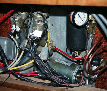
Thomas 317 After-market Compressor
These were available from Scott
Nehoda
 The
compressor is mounted in the same location as the original Dana, i.e.
tucked under the air manifold / solenoid valve assembly. You have
to drill 2 new holes in the sheetmetal tray to mount the Thomas.
The
compressor is mounted in the same location as the original Dana, i.e.
tucked under the air manifold / solenoid valve assembly. You have
to drill 2 new holes in the sheetmetal tray to mount the Thomas.
In this installation the compressor's air outlet port is connected
to an
in-line filter/water separator via a coil of copper tubing. This has
proven to be very effective in getting the moisture to condense out and
collect in the bowl of the filter, rather than in the air tank as in
the O.E. setup. I've also incorporated the rest of the Cinnebar upgrade
incl. check valve.
Electrical hook-up is identical to the Dana - one lead for +12V and
one for GND. Maximum current draw after initial start-up transient is
18 amps. (This would be when working at its maximum rated pressure of
150 psi.)
The O.E. wiring circuit, which supplies the Dana via 14 gauge wire and
a 30 amp circuit breaker, would probably be adequate but I have
followed
the advice of others who have recommended heavier gauge wiring and a
separate
relay even for the Dana, in order to minimize voltage drop over the
long
wire path from the start battery.
Richard
[INDEX] | [SUGGESTIONS]
