Front Suspension and Final Drive
[Measurements] [Rebuilt
Knuckles] [ZERK BEARINGS] [HUBLER
BEARINGS] [SEALS] [GASKETS]
[CLAMPS] [NEW CV JOINTS]
[bolts][FRONT PARTS LIST][ OFFSET SPACER] [RATIOS] [REMOVE BOOT] [RETAINER BOLTS]
1-ton Hubs and
Knuckles (Version II)
When
faced with the cost and availability of front end repairs :
ball joints
control arms
bearings
hubs
knuckles
cv joints / axles
rotors
calipers
pads
these (readily available) 200,000 mile, bearings become very attractive
take a look at this list of links:
Here
are the hub/knuckle measurements from Cinnabar.
The hub diameter is supposed to be 2.0015 to 2.0025 with no steps
or taper.The bearing inside diameter is 2.000, that means the hub is
.0015 to .0025larger than the bearing resulting in a stiff press fit.
The knuckle diameter is supposed to be 3.2510 to 3.2525 with no
more than.0015 out of round. The average diameter must be within the
3.2510 - 3.2525spec and the minimum diameter must be at least 3.2510.
The bearing size is3.250, that means the knuckle is .0010 to .0025
larger than the bearing.This is what my machinist calls an interference
fit, it presses on quiteeasily.Charles Wersal
Front
Suspension and Drive Rebuild
Front
Wheel Bearing Replacement
DRIVE LINE BOLTS From Mc Master-Carr
(3/23/05)
TORQUE - Drive line bolts - 65 ftlb
http://www.gmcmhphotos.com/photos/showphoto.php?photo=28658
http://www.mcmaster.com/
91271A644 - 12 Point Flange
Head
$8.06
$8.06 today
Cap Screw 3/8"-24 Thread, 1-1/4"
Length, Fully Threaded, Packs of
25
The above cap screw is a good replacement for GM# 394777
which is still
available from GM. The fact that it is threaded full length
is not an issue.
The torque applied to them keeps the flanges tight together.
The bolts do
not take any shear loading if tightened to spec. Denny Allen
>
> 91104A031 - Grade 5 and 8
Heavy
$5.54
$5.54 today
> Duty Spring Lock Washer 3/8"
> Screw Sz, .385" ID, .680" OD,
> .094" Min Thk, Packs of 100
Rick "who couldn't survive this hoppy without McMaster-Carr" Denney
The above washer will work but the "High Collar Lock Washer"
Mc Master-Carr#
90073A231 is the correct replacement for anyone that is
trying to keep an
accurate cross-reference. Although it is not in the our Z78
parts book this
washer is available from GM as #9439512 denny allen
FRONT END REBUILD PARTS LIST
Denny Allen
Cowichan Bay, B.C
> 1) upper A arm bushings
--Moog# K7006--concentric
--Moog# K7104--eccentric for
more caster
> 2) lower A arm bushings
--Moog# K5222
--TRW# 12299
--NAPA# NCP267-3299
> 3) Lower Balljoints
--Moog# K6215
--NAPA# NCP260-1392
> 4) upper balljoints
--Moog# K5238
--TRW# 10270
--NAPA# NCP260-1126
> 5) sway bar links
--Moog# K446
--TRW# 18048N
sway bar bushings
--Moog# K5253
--TRW# HB1158
outer tie rod ends
--Moog# ES412R
or L
--TRW# ES412L
- -Rare Parts# 25536
inner tie rod ends
--Moog# ES361R
--TRW# ES361R
--Rare Parts# 25470
Tie rod sleeve
--Moog# ES2004S
--TRW # ES2004S
> 7) Steering Box
--NAPA# 27-7519
--or use a rebuider
--or use link below and
search for steering gear
> 8) idler arm
--Moog# K5209
--TRW# 18737
--Cinnabar# 12308782
--Rare Parts# 20238
> 9) steering damper
--Moog# SSD55
Rare Parts are in Stockton, CA and only sell to businesses I
believe.
Some of the above #'s are no longer available but may work for a
cross reference.
CV Joint Replacement
Without Removing the Hubs or knuckles.
I think 66 thru 78 Toros and 67 thru 78 Eldos CV joints are the
same.Milt
Wade-Las Vegas
-----------
NEW CV JOINTS FROM EMPI
http://cgi.ebay.com/ebaymotors/ws/eBayISAPI.dll?ViewItem&sspagename=STRK%3AMEWA%3AIT&viewitem=&item=8052661096&rd=1,1
The early Toro and Eldos and GMCs were 31
spline, 79 and later are 34 spline. C.boyd
CV JOINT PROBLEMS
http://www.gmcmhphotos.com/photos/showgallery.php?cat=3634&ppuser=7
-------------
On separate occasions I removed the axles from both sides without
pulling the hubs or knuckles. After loosening the axle nut at the hubs
along with the 6 twelve-point bolts holding the axles to the final
drive
output shaft flanges (wheel still on and on the ground) jack up the
front end and remove
the wheels and twelve-point bolts. By pushing
the axles up and to the side you can pull the them out of the hub
and drop them down underneath the engine / final drive. I
remember
that on the right side it helped to take off the shock absorber
and raise the lower control arm and knuckle few inches using a bottle
jack so that the angle improved to let the axle come out. I then
took the axles to a CV rebuilding shop and let them do the dirty
work.
Good luck with yours.Phil Stewart
----------------------------
Last weekend I serviced the inner & outer CV joints on my
GMC. The outers were questionable so I used a pair from
an Eldorado I recently stripped. Remember the thread about "the
clicking noise?" It was the CV joints. (Thanks again to
Jim Bounds for the tip on this.) I power flushed the outers using clean
solvent & compressed air and laquer thinner as a final rinse, they
looked too good to disassemble so I settled for repacking and installed
the new boots. No photos on the outers.
I removed the axles according to advice rec'd on the
net. Pretty fast & easy compared to most
suspension work. R&R took about 6 hours, the disassembly,
cleaning & reassembly about 4 or so. It would probably be
quicker for someone who has done it before but I haven't.
Just for my own experiment with grease, I used Mobil 1 on all
joints except the passenger side inner. Time will be the judge on
this experiment as I used the stuff that came with the boot kits on it.
------------------------------------
Just a reminder that you do not have to take either ball joint apart to
remove the axels.
For drivers side jack the lower A frame high enough to pull the axel
from the hub and than turn the steering to the right and pull the axel
out from behind the hub. For passenger side remove the oil filter,
position the steering wheel straight ahead, jack up the A frame enough
to slide axel out of hub by moving inner end to rear where filter was
and pull
axel out through the filter area. I never remove the ball joints unless
I have to because of the chance of damaging the seals.
Steve you may have exceptionally clean solvent but I would never
clean the CV joints without taking them apart. One particle under
a ball can ruin it in a short time. How can you inspect the balls and
races with the joint together? If you have gone this far take them all
apart and carefully service them in ccordance with the manual.
Just my opinion of course but these are precision matched sets and
must be kept very clean and will greased to avoid failure. Tom
---------------------
I don't think you will find it too hard to tackle a CV joint job,
as long as you follow the book and do things carefully. A few further
thoughts however.
The bolts at the Final Drive may be pretty tight, so you might want
to loosen them slightly before getting the wheels off the ground. When
you clean the CV joint, don't use any kind of cleaning fluid on them
but
rather a clean lint free cloth. The balls can be popped out if
necessary, but be sure you get them back into their same positions as
it is easy to get them all mixed up!It takes a bit off time and care to
wipe all that grease and mess out of the joints.
If you use the plastic blue boots on reassembly, they are rather
stiff and hard, at the clamping points so it is hard to stop them from
leaking grease. I used this kind but had to redo the clamping and
finally with
double wrapping clamps and reefing them up to just below the breaking
point, they now don't leak. (don't use the pinching kind of clamp-I
don't think they can pinch tight enough). If I do it again I will
use
GM ones instead as I believe they are of a softer and different
material which allows the clamp to bite into it better. My old GM
ones were 20 years old and still good, but I replaced them just because
I was doing
the joints.
--------------------
BOOTS,
CLAMPS,--DOUBLE WRAPPING
Replace the CV boot with out removing the axle
Jack up the front of the coach, block it,
remove wheel (optional), remove the tie rod from the knuckle(optional,
but it will give you more room & flexibility), cut the old boot
off, with a snap ring pliers, EXPAND snap ring in the outer CV joint
and slide axle towards the inner plunge joint, clean as needed, install
new boot on axle, slide axle into outer CV joint, snap ring will expand
as axle is pushed into CV joint, MAKE SURE SNAP RING IS SEATED, install
grease and position CV boot, burp the air out of the boot and clamp it,
try to keep the surface for the outer clamp surface as dry as possible.
This is about an 1-1/2 hour job per side, good luck. Bob
Drewes in SESD
I got them from NAPA --
Boot Clamp (large) PUJ-3416 -- Torque to 65 in-lb.
Boot Clamp (small) PUJ-3415 Manny (no longer available)
*****************
Here are some more part numbers and sources -- Ken
http://www.gmcmhphotos.com/photos/showphoto.php?photo=4164
The NAPA part numbers are on the photo site in my album on
replacing a CV boot. But I've since bought a lifetime supply from
www.mcmaster.com
p.258.
100 ft bands - 5422k42
100 clips - 5422k43
I think that's the best option because they're useful for other
purposes also. Ken (12/31/06)
*******************
Here are some pictures of working on the boots and how
to lube them
http://www.gmcmhphotos.com/photos/showgallery.php?cat=3539
http://www.gmcmhphotos.com/photos/showgallery.php?cat=3120&ppuser=40
http://www.gmcmotorhome.com/tech/axle/index.html
------------------
On reassembly, you might want to consider reversing the shafts from
left to right as they are identical and in this way the splines at both
ends will be getting their wear points on the opposite side of the
spline, most likely not a major issue but and idea for longevity.
I believe the bolts at the final drive are a grade 8, and Wes C.
recommends that one replace them with new ones, which likely is not a
bad idea as these need to be reeffed (torqued) up very tight so they
don't come loose. For the size of bolt they are torqued very tight!
When I did mine I did it as a preventive maintance plan at 68,000
miles and 19 years on the original boots and they still looked good,
but with that age I didn't know how much longer they would go. I now
carry them
as spares but when I redo them next time I think I'll go back to new
OEM's. Claude in Victoria.
FINAL DRIVES
GASKETS
Pictures and Descriptions of the gaskets
http://www.bdub.net/FinalDriveGasket/index.html
I am familiar with the 2-part gaskets used on the final drive
cover. I also recall Max at Buskirk-Rush telling me that they have
received some that were assembled backwards, and this caused the vent
hole in the cover to be blocked. Now they always check these for proper
assembly before they install
them.
However ---- Last year I replaced the final drive fluid and gasket,
and I got the gasket from
NAPA / VICTOR: "Part number P 28883 Axle Hsg. Cover".
( Fel-Pro # RDS 55034 cover
#rds30094 final/trasn Gary Kosier)
-----------
The final drive cover gasket that comes as two pieces stapled together,
is to be installed
as though they were one gasket. Leave them stapled together and install
making sure the vent
groove in the gasket is on the same side of the final drive as the
small vent hole at the top left
side of the final drive cover.Charles Wersal
----------
The final drive cover gasket that comes as two pieces stapled
together, is to be installed as though they were one gasket. Leave them
stapled together and install making sure the vent groove in the gasket
is
on the same side of the final drive as the small vent hole at the top
left side of the final drive cover.Charles
------------
It was labelled "made by Victor Reinz (Dana)". It was a ONE PIECE
gasket, and it had the slot for the vent hole. The material was a bit
thicker than that used on the 2-piece gaskets. I looked at it and
compared
it to the old 2-piece gasket,
I only used this for the trip to Clifty Falls last April, and had no
problems with fluid leaking. The complete final drive was replaced
after that because of a failed pinion gear bearing (bearing fell apart
when we removed the retainer plate). I discovered then that this gear
was going bad when we bought the GMC, as that loud whine disappeared
after that. Now I know what a GMC is supposed to sound like. :>)
My point - this gasket does not necessarily have to be a 2-piece
part. I can't really figure out the function of that uncut section over
the vent passage, unless it was to make this passage smaller (?).
Just my opinion.Erv Troyer
GMC MOTORHOME FINAL DRIVE RATIOS
Here is a table of Final Drive Ratios and various Tires
http://www.gmcmhphotos.com/photos/showgallery.php?cat=3334
Here is a table of over-all drive ratios by KenH
http://www.gmcmhphotos.com/photos/odds-n-ends/p52914-overall-drive-ratios.html
| FINAL RATIO |
RPM @ |
RPM @ |
RPM @ |
RPM @ |
RPM @ |
RPM @ |
TEETH |
TEETH |
|
50 MPH |
55 MPH |
60 MPH |
65 MPH |
70 MPH |
75 MPH |
PINION |
RING |
| TORO
2.73 |
1690
|
1859
|
2027
|
2196
|
2365
|
2534
|
15 |
41 |
| ORIGINAL 3.07 |
1900 |
2090 |
2280 |
2470 |
2660 |
2850 |
14 |
43 |
|
3.42 |
2125 |
2350 |
2550 |
2760 |
2980 |
3150 |
12 |
41 |
| CASPRO 3.50 |
|
|
|
|
|
|
57 CHAIN |
65 |
|
3.50 |
2166 |
2394 |
2600 |
2812 |
3032 |
3248 |
|
|
|
3.55 |
2200 |
2420 |
2640 |
2860 |
3080 |
3300 |
11 |
39 |
| DUNN
3.63 |
2247
|
2471
|
2695
|
2919
|
3144
|
3368
|
55 CHAIN |
65 |
|
3.66 |
2274 |
2500 |
2730 |
2955 |
3183 |
3412 |
|
|
|
3.70 |
2300 |
2530 |
2760 |
2990 |
3220 |
3450 |
10 |
37 |
THE ABOVE FIGURES WERE DERIVED FROM VARIOUS METHODS
TIRES: 8.75X16.5 OT 225/75X16
Your site was very helpful. You might add the division formula that
R Black
posted on calculating the ratio
."Count the teeth on the two sprockets and divide the little number
into the larger."
I had 41 teeth on the ring gear and 15 teeth
on the pinion gear. 41 divided by 15 = 2.73
Also the note that Milton Wade posted that the "If I remember
correctly the amount of teeth on both the pinion and ring gear are on
the edge of the ring gear." I found 41-15 on the side of my ring gear
and I counted 41on the ring gear\Charles Wersal
-----------------
The Caspro 3.42 setup does not use the chain drive gear from a TH325
and the stock TH425 driven gear. But it does appear that some
rebuilders are using this, infact the gears might not be the
same thickness.
----------------
CHAIN FINAL DRIVE RATIOS
Caspro (65/57) x 3.07 = 3.50
Dunn (65/55) x 3.07 = 3.63
I have a Dunn trans in mine which I took the cover off to look at it
before I installed it.Caspro has a 57 tooth sprocket at the torque
converter and the Dunn has a 55 tooth sprocket.They both have a 65
tooth sprocket on the front of the trans.A few years ago someone had
the formula of how to figure out what the ratio is in the GMCMM
magazine,anyway the Dunn
ratio came out to 3.63-1 and the Caspro was 3.50-1.HTH Milt
-------------
NEW POWER DRIVE RATIO---Caspro Company
It's not very often that a revolutionary new component is introduced
for the GMC
motorhome. Caspro, who offers other unique GMC components has
introduced a new transmission gear kit, that effectively changes the
OEM final drive ratio from 3.07 to 3.50 and for those members who
installed the 3.21 final drive the change goes to 3.66. The 3.07 gear
ratio was originally designed for the 1968-78 Oldsmobile Toronado that
was less than half the weight
and wind resistance of the GMC motorhome. Furthermore, the Toronado had
15 inch wheels while the motorhome has 16 1/2 inch wheels and larger
diameter tires. Consequently, the motorhome engine is always struggling
to do its job, because it cannot turn at high enough revolutions to
generate its
rated power and suffers under the inadequate torque multiplication of
the
overall drive gearing.
This change allows the engine to operate more nearly at its most
efficient torque speed rpm (2550 rpm). In the driving speed range of
55-70 mph there are three very significant gains that are achieved.
First the engine is permitted to turn at a slightly higher RPM, which
enables it to generate approximately 35 more horsepower at the same
road speed. Second, the mechanical torque multiplication to the wheels
is increased by 14% for an average total increase of 72 lb. ft. of
torque. Third, the torque converter load, under normal conditions, is
reduced which minimizes heat, thus extending the
life of the transmission. It is important to understand that this
mechanical
(drive-ratio) torque increase occurs in the power train after the
engine
horsepower increase, and therefore the delivered benefits are additive.
The above benefits are for the 455 stock engine, the 403 engine will be
in direct proportion to the ratio of engine sizes that is 89%. At 65
mph
with the 3.21 final drive, there is a 60 HP increase over the stock
engine
and the stock 3.07 final drive.
This modification requires removal of the transmission and returning
your old turbine shaft. The new drive-sprocket and drive shaft assembly
kit
also includes a new chain and sealant, along with new ball bearing,
snap
ring and seal that are assembled to the exchange shaft. The complete
kit
will cost $875.00 plus a refundable $250.00 core charge (your old
turbine
shaft must be returned for the refund) plus shipping. The kit will be
available by the end of March, 93. Contact:
Chuck Stoddard
Caspro Company
P.O. Box 390
Novelty, Ohio 44072
216-423-0809
Installed at your own home garage, the costs are:
$1195 final drive (3.42); final drive core charge $150; final drive
crate
$50; speedometer adaptor $75 and shipping of about $60 UPS. Ship
the old
unit back for about $60 and get your core charge and crate refund of
$200.
Kanomata prices at the Mt Hood GMCMI rally last fall were:
3.55 drive unit $1190
3.70 drive unit $1390
Speedometer adaptor $70
Core deposit $300
plus shipping
stated warranty 4 years or 48,000 miles.
JR Wheeler
Regarding axle ratios, I personally feel there is nothing to lose in
going to as low a ratio as is possible. Certainly anything up to a 3.90
or so would not be too much, camper special pickup trucks routinely use
4.11 and 4.56 ratios after all.
GM recommended a ratio of 3.42 in the early 1970's on most full size
car lines with 454-455 engines in the trailer towing packages. This was
considered adequate to tow a 7000 lb travel trailer with, say, a
Caprice or LeSabre. 1973 up Three Quarter and One Ton pickups with
Camper Special Equipment had a mandatory 3.73 ratio as a minimum
requirement.
For best economy for travelling under a heavy load it is desirable
to
gear a vehicle for operation at or up to ~400 rpm below the net torque
peak
at the usual road speed. This assumes the engine makes adequate torque
to
carry the load at that rpm. I generally would shoot for a 60 mph
cruising
speed, and appropriate gearing for that. Driving a large vehicle over
60
starts to really use a lot of power and fuel, and setting them up for
say
75 mph cruise is kind of pointless, theres not much scope for good
economy
at that speed anyhow.
Aerodynamic drag is the largest issue from a cruising perspective.
According to a chart I have in a GMC Dealer Data Book heres the Air
Resistance Demand Horsepower figures between 30 and 70 MPH for a
relatively square nosed vehicle of 60 sq/ft frontal area.
30 7.8
35 12.3
40 18.4
45 26.2
47 29.9
49 33.8
50 36.0
52 40.4
54 45.3
56 50.5
58 56.1
60 62.1
65 79.0
70 98.7
As you can see, horsepower just for wind drag is very significant.
Driving 56 mph takes about half the output to overcome the wind that 70
mph does. Rolling Drag losses go up proportional to road speed/weight,
and not exponentially as wind drag. Twice as fast or twice the weight
= twice the drag for weight and rolling resistance for the most part.
Takes about 20HP to overcome rolling resistance of a GMC at 60-65 MPH.
At 30 MPH it would be more like 10HP.
Another thing to consider is there is approximately 145-160 net HP
availible in the first place from which you can deduct the drag;-)
I would definitely think the factory installed 3.07 is too tall for
the application. The GMC would be 'driveable' right down to a 2.41 in
all likelihood, but with disasterous economy and performance
implications. One real gas eater is operating an engine below 7" Hg or
thereabouts vacuum readings- your power enrichment system is activated
and mixture strengths are increased quite drastically and this pulls
fuel economy way down. If a higher numerically ratio set of gears
permits you to cruise and handle minor grades and headwinds without a
susbstantial loss of manifold
vacuum, you will get better economy. Liberal use of second gear can
help
also. Keep vacuum over 8" as much as possible.
Just for reference, the tires on a GMC rolls about 675 revolutions
per mile. Multiplying 675 times the axle ratio gives the engine RPM at
60 MPH. 675 x 3.07 = 2072.25 rpm @ 60 MPH.
Dividing 2072/60 = 34.5 rpm per MPH. At 100 MPH the GMC would only
do
3450 rpm at this rate- thats a pretty tall ratio! Of course there is
slight
slip at the torque converter, so the actual figure is slightly higher
as
indicated on the tachometer.
The torque peak of the 455 is about 2800 RPM as I recall, this
means a range between 2400-2800 RPM would be the ideal for cruise
economy. 2800/675 = 4.14, which would be about the lowest ratio you'd
want, and 2400/675 = 3.55 which would likely be the ideal, at 60 mph
average cruise speed in any event. A 3.42 is not far off that, and with
slight converter slippage would be pretty darn close to ideal.
I've seen the Caspro Power Drive Chain system and the aforementioned
box for switch pitch control made by the Toro List member and they are
both excellent units and I will be using both myself. The switch pitch
converter is desirable if you have an opportunity to obtain one, not
vital, but a definite refinement.
Anyhow, basically to sum, the benefits of a high numerically ratio
axle are substantial for the typical owner, and although even a
2.73/3.07 etc. will work and drive acceptibly with adequate
performance, the
penalties for economy and performance would probably substantially pay
the costs of an upgraded axle ratio in a short time. Go for the 3.21
3.42 3.54 3.73 if you can get them!
>Here are my questions. With a 3.07 at what engine rpm am I
running at
>22 mph in first gear?
1900
What RPM am I turning at 42 mph in second gear?
2200
>
>Now my next set of questions. Same speeds in the same
gear with a
>3.42?
2125/2450
These figures are approximate- if you just swapped axles and did not
make other changes, if those are the speeds your GMC currently
upshifts, it will continue to do them at pretty much the same RPM, but
a slightly lower road speed.
First gear is about a 2.5 ratio and second is about 1.5. If you
multiply top gear RPM by these figures you can determine the RPM in the
lower gears.
Hope this helps! Brent
GMC Rut Running
The GMC motorhome jumps in and out of ruts in the road because the
front wheels do not run in the same track as the rear wheels.
This is an original design constraint of the GMC. Slack or
looseness in the front suspension, steering and rear suspension
aggravates this
condition. Tires can also affect this condition.
Extended
wheels / Spacers
I also am only able to navigate my driveway on dry pavement. I
put
spacers
on the front wheels a couple years ago and then could not get up even
on dry pavement. It upset the geometry enough to cause the front
tires
to alternately spin and at the same time bounce the front end of the
coach to the right. Almost wound up in my neighbors yard over
about a
30 foot cliff. Someone suggested backing up, which I mastered but
always had a lump in my stomach each time. Finally gave up and
took
off the
spacers. Now I am
back to square one. Enjoy the link.
http://www.gmcmhphotos.com/photos/showgallery.php?cat=3773
Bob Sobrito
----------------------------
Dave Mumert
Just for information, the distance from the center of the bearing to
the wheel mounting face of the hub is 4.28", the offset for Alcoa
wheels is 4.567". So the center of the wheel is about .29" inboard of
the center
of the bearing pair.
--------------------
It is clear that GMC had the technology to change the offset of the GMC
/ Toronado front wheel drive but chose not to. Here is a picture
of the offsets talked about by DaveM , above:
http://www.gmcmhphotos.com/photos/showphoto.php?photo=19160&cat=3619
----------------------------------
I held back getting into the
spacers opting to
watch and see how it went. In standing on the sidelines though I
have
been maintaining many coaches with them and on occasion have installed
them. As was reported, I also saw no degridation in the
reliability of
the front bearing assembly and though it would be easy to have sided
with the engineers that said the pressure would destroy the integrity
of the assembly it was good I did not say that because it does not seem
to play out.
I will say though that most people opted for
spacers
because they felt they had some driving problem they thought the
spacers
would cure. I have to say this should not be the reason to get
them.
If you have driving issues, you really need to go back to basics and
solve the problem first. Bone stock, the GMC will track doen the
road
as good as any car runnign whatever speed you like with 2 fingers on
the
wheel. If yors does not then there
is a
problem with the system that needs more than the "bandaide" effect you
would have in putting on
spacers. Yes,
spacers
may mask a problem making it more palitable but the problem would still
be there. Solve your issues first then if you feel froggy and
wanna do
it then get
spacers and see if you can add on
perfection. JimB
------------------------------------
Don't blame the spacer for not being able to go up the hill.Your front
end is worn to the point that your toe in is great enough to cause
enough sliding.Repair it and you'll not have to tell people that the
spacers don't work. JimK
-------------------------------------------
I have a wandering problem with mine I am trying to resolve as well. I
have Lenzi knuckles and hubs,Lenzi relay lever, idler arm, offset
bushings,
wheel spacers,new
BF Goodrich rag walls, new ball joints and just did a string alignment
and I am still not satisfied with the handling. BobW
--------------------------------
Extended wheels can correct the tracking. Machining a
hub-centered adapter for these wheels is needed because extended wheels
available are not hub-centered but hang from the stud bolts. The
load of the GMC wears these bolt holes and causes other problems.
The extended wheels have been calculated to increase the loading on the
hubs and bearings( already at maximum ) by 450% ! An
interesting article in the GMC Motorhome News (September 1998) by
Chuck Aulgur, Mechanical engineer, describes the technical aspects of
this mounting. The results spacers do not
significantly reduce the life of the front bearings, Hubs, etc.
Users of these wheels say this eliminates the rut running.
---------------------
Dave wrote: You are absolutely correct that the steering geometry (and
suspension geometry) will be changed and this is a major concern. For
example, the ball joints and A-arm bushings will see higher loading in
the plane parallel to the ground. I mentioned before that the torsion
bar will receive higher
torsional stress. Torque steer will probably become more noticeable and
there is a host of other effects that will have to be looked at and
maybe the conclusion will be that it is just not worth it. Even
if we conclude that a change may be beneficial, chances are that
there is not a wheel available with the offset we need. But at least we
will know something. Either the factory offset is optimal or
it isn't. Whether we can
do something about it or not is another subject.
Thanks Scott for taking the time for pictures and dimensions. The
numbers are not exact but close enough for me to draw my conclusion.
The tread centerline is running just inboard of the inboard bearing
but I can't believe how close together the two bearings are! They are
so close together they may as well be called one big damn
bearing! If I were to follow through and have the
offset match the bearing center, then the wheel could be moved out
about 1 to 1.25 inch. This may help waggle some but I feel it isn't
enough to bother. OK, so I'm the dufuss. Whether this small change
would help bearing loads or not, I cannot say. At this point I am more
inclined to believe the offset is correct for this front end geometry.
Man, I can't believe that bearing spacing. Don't be a hot rod in the
corners is all I can say.
So now I am satisfied, and I am leaving my front Alcoas alone. Dave
-------------------------------
Dave, (and now Brent), I think that you have it basically
correct here. I have no expertise in the theoretical pro's and
con's of this issue but I do have a bit of experience. There are at
least a half dozen people who have run a fair number of miles on the
wide rims. Mike Mayo in Colorado has (I think) around 20,000 miles on
his coach (I tried to call him to confirm the mileage but he was out).
Jim Robertson in Los Osos has over 10,000 miles (his coach was the one
recently noted in a posting for sale with the Cadillac 500 engine -
there
was a picture of it with the wheels). My belief is that the front
bearings
can indeed handle the stresses. This assumes that people keep their
bearings
well greased and change them out at 25,000
miles. Whether they weaken the ability of the front end to handle a
severe bump at high speed . . . who knows?
OFFSET SPACER
 There
is a new
player in the spacer arena,
Correct Track (no longer in business) .
Thanks to Arch for the picture. The picture shows a lip to hub
center the wheel. Now for bearings: My bearings normaly run about
20 to 25 degrees aboveair temp. It is 62 here now and pass side bearing
is
at 86 drivers side is at 87. I have checked them several times today.
We
will have to see long term but I am not seeing heat that looks bad.Arch
There
is a new
player in the spacer arena,
Correct Track (no longer in business) .
Thanks to Arch for the picture. The picture shows a lip to hub
center the wheel. Now for bearings: My bearings normaly run about
20 to 25 degrees aboveair temp. It is 62 here now and pass side bearing
is
at 86 drivers side is at 87. I have checked them several times today.
We
will have to see long term but I am not seeing heat that looks bad.Arch
I am the one who is the sales Rep for Correctract Wheel Spacers and
have sold them at Cody Wy. and Nashville. As far as weakness in
the GMC front wheel bearings, as I see it the weakest link in the wheel
bearings is the owner. As far as testing the spacers, I have logged
10,000
miles on them with no ill effects on the bearings.Gene Ransom
-------------
Bobby Moore of Louisville, my brakes (& other stuff) guru, has
arranged to have 2" spacers made. The machine shop is Highland
Machine Tool in Floyds Knob, IN. It's now run by Jim Bezy, son
of the old GMCer Ed Bezy whom many
of you may have known. Both Bobby and JR Slaten drove to
Lakepoint with them installed and are very happy. Peg Moore drove
part of the way and she was getting the other wives all excited too
-- she loved the way the coach drove. My wife's on my back too
now!
The spacers are made of 12L14 cold rolled steel, a common grade with no
special characteristics except that it should be adequate for this
application. The installed studs are standard grade 8 just like
you'd install in your hubs if you were replacing them for installation
of Alcoa wheels.
Jim has not weighed the adapters and doesn't have one on hand.
He'll weigh the next one he makes and let me know so I can post it
here. He did comment that after all the holes are drilled it's
"not nearly as heavy as it looks".
----------------------
The wheels to use are Alcoa 16 x 7's designed for Ford trucks. They get
the fronts very close to the widths of the back wheels. They are NOT
hub centering. Some people have used them this way but I chose to purchase a centering hub from Aptos Tool Co in
Aptos, CA for $95. This hub is made by a GMC owner who owns
a machine shop and made a set for himself (I don't know how many miles
he has
on his own wheels). (these no longer seem to be available).
I had the wheels and hub/spacers on the coach for a relatively short
time to test the setup. I think that there is no doubt that they help
the rut stability problem. However, they do indeed change the geometry
of the front end. Torque steer is definitely an issue. They clearly
accentuated a left to left-right-left (or is it right-left-right) front
drive wiggle upon starting out. I talked about with this with Mike
Mayo, and he felt that this was the only significant negative to the
wide wheels. I found the ride to be harsher and I felt the bumps more
extremely. This may have been my coach or it may be the offset. Likely
it is something that can be adjusted out of the coach with some
creative alignment work. I took them off the coach because I will
be doing a lot of work on the front end and wanted to be sure
that any problems are not related to the wide rims. My intention is to
try them again once everything is overhauled - bearings, hubs
etc. My suggestion for the perfect set up is to widen
the frame at the front, which is in agreement with Brent's most recent
posting. This would mean not only changing the frame, but getting
custom sway bars, axles etc. It would probably work superbly
though. If anyone would
like to seriously experiment with my rims on their coach, then please
get
in touch.Vic Marks
-----------------------------
Four bagger modifications change the side to side roll
stability of the GMC but do almost nothing for the tracking
problem.
The four baggers in essence remove the bogie action on the GMC and
convert them into four independent wheels.gene
THE GMC MANUAL X-7725
PAGE #A-22 IS WRONG FOR BALL JOINT TORQUE
I torqued the upper ball joint stud nut according to the GMC Manual
X-7725, page #A-22 and stripped the threads. It list 100-125 Ft.
Lbs. for the upper and 40-60 Ft. Lbs. for the lower. Are these
numbers reversed. After a closer look I realized that the lower
ball joint stud is larger than than the top. Makes no sense to me
that the torque spec for the lower ball joint stud would be less for a
larger stud.
Gary Bovee
THE GMC MANUAL X-7525 PAGE
#3A-22 IS CORRECT FOR BALL JOINT TORQUE.
. In my manual,(7525) on page 3A-22 it shows that the upper
is 40-60 ft pounds and the lower is 100-125 ft pounds. emery
Good catch Gary and Emery, another error in the manuals
Correct part numbers are:
Lower K-6215, $75.94 each
Upper K-5238, $46.95 each
Bought them at my local Miracle miles parts store.
NAPA or Auto Zone-------the latter I think.
The Moog number for the offset upper bushing is K-7104. The number
for
the regular bushing is K-7006.
The other Jim 78GB 500Cad
Ball Joint Replacement
Do NOT drill all the way through the A-arm
when replacing riveted ball joints. Actually, if you're following
the
"Book", it doesn't say to drill all the way through. Good auto
shop practice
is (wearing safety glasses):
1. Center punch the rivet.
2. Drill a small pilot hole (I use double-ended 1/8" bits,
cheap) about
1/4"-3/8" into the rivet. Object here is to get said hole as
CENTERED as you
can. This is quick.
3. Now, get out a drill bit which is slightly
LARGER than the rivet
diameter, and slowly enlarge the 1/8" hole you just made. When
you get down
around the level of the A-arm, stop frequently and examine the
hole. When you
contact the A-arm, it will show as a line or crack part way around the
hole
you're making. If you're real lucky, the hole will be perfectly
concentric
with the rivet hole, and the rivet head will come off on your drill
bit.
Usually....
4. When the hole contacts the A-arm, stop drilling, get out
a large sharp
cold chisel and BFH (big f... hammer). Remove the rest of the
rivet head.
The closer to centered your drill holes are, the easier this will be.
5. Finally, drive out the headless rivet with
a punch or drift.
This is the "right" way to remove riveted ball joints
on
a GMC or any other car, and causes minimal scarring of the A-arm, and
no
distortion of the rivet hole.HTH.Rick
Do yourself a big favor and use 3/8 hardware and when you're
finished, spot weld the bolts. It isn't
any harder to grind a spot weld off that it was to grind off the
original rivits if you ever have to replace them. Easier in
fact. Also, while you have the ball joint accessable,
thread the castle nut on, grip it
with a socket and pump that thing full of synthetic grease while
rotating the joint through all of it's travel. Do this several
times. It's the best insurance you'll ever get that the thing has
been properly
pre-lubed. It also gives you an opportunity to check the
zerk flow.Steve
LOWER CONTROL ARM FAILURE
If your lower ball joints are held to the control arms with bolts,
your lower control arm is at risk. The holes for these bolts
might be egg shaped from loose bolts or improperly drilled out rivets.
This puts a lot of stress on the ball joint hole at the end of the
lower control arm and eventually failure of the control arm. I
have heard of rivets becoming loose but it seems most of the
failures have come after maintenance has replaced the lower ball joint.
WHAT TO DO
1) Check the bolts on the upper and lower ball joints at every lube and
bearing check.
2) Check the tip of the lower control arm with a sharp scribe or at
least a finger nail looking for cracks.
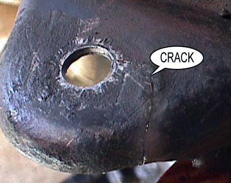 The crack
in the control arm shown in the picture could have easily been found
this way. This control arm was from an active GMC and had not yet
failed. The GMCMM article Jan99, points out that this procedure will
not find hairline cracks. You would need to tear down the
suspension and carefully check the area around the hole.
The crack
in the control arm shown in the picture could have easily been found
this way. This control arm was from an active GMC and had not yet
failed. The GMCMM article Jan99, points out that this procedure will
not find hairline cracks. You would need to tear down the
suspension and carefully check the area around the hole.
3) If the bolts will not stay tight, the ball joint should be
replaced and possibly drilled out for larger tight bolts. ( I am
not
sure green goop (locktight #----------) will help, but it cannot hurt)
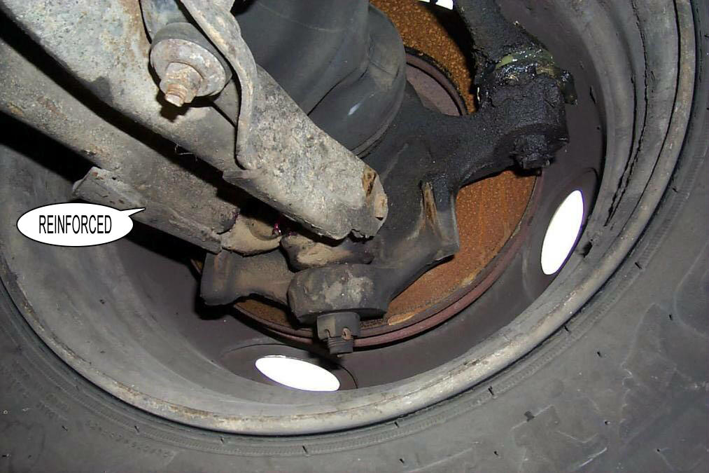 Standard
A-Frame
Standard
A-Frame
This picture shows the standard reinforcement that GMC provided on the
A-frames. After-market suppliers can provide even more
reinforcements. Bill
-----------------------------
The question keeps coming up on the net as to why the front
wheels are not in line with the back? IT WAS COST. In order to save
money GM used off the shelf control arms they already had, only to cut
costs. They soon had a lot of trouble the 73-74 had seven small patches
were then welded on the weak
spots. from the 75s on they made a little better plates thru the 78s,
however GM again fell short and only reinforced the three sides of the
hex and its the top three sides that brake out. I have photo of most of
the control arms 73 Thu 78 years showing the patches and the break
outs. I found out the hard way, I for the first time ever had a local
garage work on my motorhome [bad move ]for they installed the new
torsion
bars in backwards. At high speed about 150 miles later both bars strip
out the control arms at the same time. Yes, there is a front and rear
to the torsion bars I called GM in Detroit and they nor any dealers I
called could tell me how they went in! I called Cinnabar,Wes at that
time
said he did not know. Well, for what it's worth there is a left and
right
and the ends are stamped with a R or L next to a little arrow, that end
goes to the front. Should you ever need to replacement you can use
Toronado
or Eldorado lower control arms but be sure to have them reinforced and
the ball joint bolts welded by someone that knows how. Jim Anstett
Loveland
Colorado
-------------------------------
Control Arm Sources
Cinnabar
They have rebuilt control arms for $459 with new ball
joints and bushings. If your old control arms can be rebuilt they
will give you $200 for the core return. These must be GMC
original reinforced control arms.
Buskirk
I just got off the phone to Buskirk and talked to his chief Mechanic
Max. they do have the HD arms but they come in a kit including the new
torsion bars. They have to be installed at Buskirks. max does not think
they are suitable for anything but the stretch coaches.Thomas
He says that if they find any cracks they have them repaired at a
good welding shop. You do not need new ones.
Front Bearing
Service / Sources
KNUCKLE
ZERK MOUNTING
(100,000 mile bearings)
There is a poorly kept secret ( only the 300 who go to rallies know,
because the talks are never published;>) that the bearings on the
GMC can go well over 100,000 miles without any problems.
the most traumatic thing you can do to the front end of your GMC is to
grease the bearings by removing the hub and Knuckle to check and remove
the bearings, and we are supposed to do this every 25,000 miles.
Every front end,boot, taper, knuckle, socket, drive line bolt and
bearing are stressed to the max and the front end alignment is almost
always compromised. Yet, this is the traditional GMC/Thoma method
for bearing maintenance.
THE ZERK
Our forefathers knew that removing the
bearings was a
problem and in 1974 published and used a technique to grease the
bearings in-place.
Alex Birch and contributed by
Kosier.
http://www.gmcmhphotos.com/photos/showphoto.php?photo=5987
Walter Wallace
http://gmcmotorhome.info/wallace1.html
What they did not have was a unified way to grease the Zerk and would
often blow out the inside seal with too much grease.
Dave Lenzi has come up with a unified approach to using the Zerk to
grease the bearings in-place, and WiperMan,(KenH) has published a
description on how to use the Zerk.
http://www.gmcmhphotos.com/photos/showgallery.php?cat=4641
In 2008, I broached the question " could we drill our knuckles,
in-place, to add THE ZERK without removing the knuckle. Mr.
Druber (gutsy guy) answered back that he had done his own knuckles and
figured it would be possible to do this modification ,in-place
********************************
I believe the knuckles can be drilled for the zerk
quite easily without removingthe knuckles.
Last fall
(2007), I serviced
the bearings and installed zerks to grease nexttime per Dave's
recommendations. It is easy to see (or
measure) where the
spacer islocated in the knuckle when it is out of the knuckle. I took a center punch andpunched the knuckle
right in the center of where the spacer
is when it is installed. I then got a 6" long 1/8" drill bit from
Grainger's and drilled a hole from the inside
out, that is, from the bearing side out, then installed a
press in zerk. To finish the job, I ground
a groove around the periphery of the
spacer, and across the OD anddown the sides with a Dremel grinder to
provide a grease
path from the newly drilled hole to the bearings.
This was with Dave's blessing via a telephone conversation we
had before doing it.
This was done with the knuckles off, but there is no reason
whyit couldn't be done with the knuckles mounted on the coach
with everything removed. RayS
*******************************
So I contacted my friend,Bob Hardeman, a local GMC machinist, to
develop an appliance that we could use to drill our knuckles (in-place
or removed) so we could add THE ZERK ourselves.
Here are the first pictures of this on-going development.
http://www.gmcmhphotos.com/photos/showphoto.php?photo=28898
Emory's excellent article on how to do your own Zerk
modification.
http://www.gmcmi.com/mem-bers/Newsletters/109.pdf
gene
Wheel Bearing Sources
Where do I purchase and what Front Wheel Bearings do I need?
Jim Kanomata
http://www.gmcrvparts.com/
Cinnibar and Gateway sell 'matched' sets of Timken wheel
bearings. These include a spacer ring that installs between the
two cones whose thickness dictates the assembled axial clearance of
.0095". The bearings will have this hand etched on the
spacer. They cost about $80 per set including inner and outer
seals. (CAUTION: Do not
mix these bearing parts with any
others as this will change the clearances.)
Why is that important you ask? Good question. The
outside
of the hub should measure from 2.0015" to 2.0020". The inside
diameter of the bearing that I have, measures 1.970". If I
were to press that bearing on a hub with maximum outside dimension of
2.0020" there would be a.032" interference fit. Thats pretty
tight and would reduce the axial clearance of the bearing by some
amount. How much? I don't really know, however the cinnabar
engineers
have run tests on the various bearings with maximum and minimum
dimensions
for both the hub, knuckle and bearing and decided that in the worst
case
of each, an axial clearance of .0095" is the minimum
clearance that can be safely used.
Cinnabars part number - 12351677
Gateway's part number -
Others to use in a pinch: (same bearings but not clearanced for our
application) Use at your own risk!!
Bower/BCA--------------------------- A-23
CR -------------------------------------- BR-23
J.C. Whitney------------------------- 38-0649-P
New Departure---------------------- S-77
Timken--------------------------------- 23 Specify .0095 axial
clearance
NAPA---------------------------------- Set-23
Federal-------------------------------- A-23
SEAL PROBLEM (4/10)
For those of you that were at the last GMCMI rally in Montgomery, and
attended Dave Lenzi's session on front wheel bearings, you may recall
that he and others had noticed a change in the way they manufacture
that inner seal (the one that seals against the CV joint). The inner
portion of the steel portion of the seal, instead of being just
straight, in some cases has been manufactured with a slight curl-up
lip. This lip is just high enough that, when set properly can
make
contact with the bearing cage. This contact makes for steel
shavings
that can get into the inner bearing and cause failure. That is why the
grease on my left side bearings looked darker than the right...it has
some steel shavings mixed in with it. Fortunately, the contact
was
quite minor and did not create enough to cause a failure, or even
any
noticeable damage to the bearings or races.
I talked with Dave some about this. It seems that National is *one* of
the only brands making the correct seal for our GMC. It is
National
Seal #5123. This seal does NOT have the turned up lip that can
cause
us problems. Things have changed since I did these bearings 6 yrs
ago,
including the way we install the seal. Had I installed the seal
(a
Chicago Rawhide seal with the lip) using todays method of referencing
off of the knuckle, the seal would have been deep enough that it would
have made significant contact with the bearing...perhaps leading to
catastrophic failure.
My point, if you are not sure of the seals that you installed
last
time, maybe you better check them. I have posted pics of the two
seals...my old seal with the "lip" and the new seal National #5123 on
the GMC photo site. It may be hard to make out. It is hard to
see, but
the difference can be "felt".
Larry
http://www.gmcmhphotos.com/photos/showgallery.php?cat=5446
--
Here is some more information from Dave
Lenzi about the seal problem. provided
by CharlesW
http://www.gmcmhphotos.com/photos/showphoto.php?photo=33538&title=pict0258&cat=5450
------------------
GMCMI parts list shows:
Inner is NAPA 47471.
Outer is NAPA 47470.
Paul Bartz
---------------
Information on the seals only.
Front inboard---National# 5123, C/R# 25515
Front outboard---National# 5109, C/R# 24888, Victor#
47470 Denny Allen
Inner seal is Federal 5123, national 5123, NAPA 47471, or Delco
290-19.
Outer seal is Federal 5109, National 5109, NAPA 47470, or Delco 290-17
Tom Warner
REBUILT KNUCKLES
Price $125.00 each with your
old knuckle as a trade in.
Ken re-sleeves the knuckle with drill stem pipe. Lawrence
ROTORS
What I bought from JCW was a rotor for an eldorado.
I had the center bored to the GMC size. Then turned an arbor to a
snug fit in the centerhole,put the two rotors face-to-face on the arbor
and used the GMC rotor as a drill jig. Voila, instant GMC front
brake rotor. Works for the rear discs, too.Gary Kosier
Remove
Bearings with
out removing the Knuckles
I did not know this was possible until I saw it done at the Ukiah
Rally. Several of the the senior GMC owners, say they do this to
repack the bearings. If there are other problems like the CV
joints and Boots, they will then remove the knuckle. gene
Pictures of bearing replace without removing the Knuckles
http://www.gmcmhphotos.com/photos/showgallery.php?cat=3224
-------------------
SETTING THE SEAL
The inner seal for the front wheel bearings has two lips that seal the
bearing. One lip prevents the bearing grease from leaving
the bearing housing, and the other lip mates with the machined surface
on the CV joint to prevent dirt/water etc. from entering the bearing
housing. The placement of the inner seal is correct when the metal of
the seal is FLUSH with the surface of the knuckle. The
lip of the seal that protrudes away from the metal of the
seal, the lip that contacts the CV joint flange, is .150". On a CR
(Chicago Rawhide) seal, #25515, the width of the metal part of the
seal is approx. 1/4". Some seal may vary in this width, it is no big
deal, as there is at least 3/8 of surface in the knuckle for the seal
to set in, before it contacts the cup of the bearing. The critical
dimension
is installing the metal of the seal flush with the knuckle surface, so
that both lips of the seal are positioned correctly.
What to use to install this seal properly. I have a seal installer.
But, you can easily make or have someone make a seal installer. Start
with some 1/2" thick, high density poly or plastic sheet. Cut a 3 1/2"
OD round piece. On one side of this piece, using a lathe or milling
machine, cut out an area 2 15/16 across, 1/4 deep. To install the seal,
place it in this recessed area of the seal
installer, and tap the seal into the knuckle until the plastic contacts
or bottoms out on the surface of the knuckle. You do not have to file
the seal or the knuckle, it is rounded enough to start, if you tap
carefully. The seal is now at the proper depth.
Before installing the CV joint/axle shaft, take a small amount of the
bearing grease that you are using and grease both lips of the seal.
Also put a light coat of grease on the surfaces of the CV joint that
will contact the seal lips. When installing the axle shaft into the
knuckle, push the CV joint/spline shaft into the spline, in one
continuous motion, until it contacts the bearing. Hold
the shaft at that position, do not let it slide back towards the final
drive, and put the axle nut on and snug it up, so that the shaft does
not slide back & forth. If you let the CV joint and shaft assembly
ride back & forth in the seal, you will double over the seal lip
that is in contact with the shaft portion of the CV joint, and you will
have a grease leaker. This seal lip needs to angle towards the bearing
to have the proper seal. It will have this angle if you push the axle
shaft in all the way, and hold it there. I have seen a number of
these lips doubled over. Get someone to help you, if needed, but
shove the shaft completely in, and keep it there.
The outer seal, CR # 24888, gets installed when the
three bolt retainer is bolted up. Put a light coating of grease on
the lip of the seal. Run these three bolts up evenly, and make sure the
seal is sliding in evenly. Watch carefully how you place this seal,
after
you lay the retainer in. The "rubber" side of the seal should lay
against
the retainer. Wording it in a different way, the "open" side of the
seal
should face the bearing, and not the retainer. Watch it, some
illustrations show it wrong. I have also seen some outer seals
installed backwards.
Again, a grease leaker. Bob Drewes
Seal setter Tool - through the knuckle
http://www.bdub.net/seal-tool/
DAVE LENZI'S SEAL SETTING TOOL
Dave Lenzi is doing so many new things for the GMC and I hope
he is getting a lot of business and credit for his innovation.
Here is one of the small things he talked about ( almost a side light).
He talked about how most of us are setting the seal to the CV
joint -- in the wrong way.
I have posted his handouts and maybe more importantly , my
interpretation of what he said about this subject.
http://www.gmcmhphotos.com/photos/data/3221/Dave_Lenzi_s_seal_tool.pdf
This is not a video as it says, it is a pdf format so that you can blow
it up to see some of the detail.
All of the credit for this goes to Dave Lenzi, and I hope I have not
made any huge mistakes ;>)
http://www.gmcmhphotos.com/photos/showgallery.php?cat=3221
Retainer Bolt Removal and Replacement
Here is a clever bolt replacement made by Terry Skinner, these
are self aligning and easy to insert and remove
http://www.gmcmhphotos.com/photos/showgallery.php?cat=3246&ppuser=4
The OEM bolts can be held in place with small rubber O rings so that
they are easier to get started when assembling the knuckle and hub.
OTC927 / Thoma
Bearing Puller Comparison
[TOOLS] [OTC] [THOMA]
CASE HISTORIES [1] [2]
[3] [4]
There used to be three suppliers for bearing puller tools for the
GMC front bearings. All of these use comparable Split Rings
that clamp over the bearings. Now there are none
The early suppliers were:
Tom Warner $200
Winterfield $600
Ken Thoma $500
OTC927 PULLERS
The first two pullers use the OTC927 puller to attach to the Split
Ring. This is the same operation that is described in the GMC
Service Manual. This procedure has not changed in the past 20
years. It is
possible to use an impact wrench with this puller if you use an 8
point socket ( or the following procedure) to drive the square end of
the OTC puller. Since there is no thrust washer or center hole
in the plug in the center of the bearings, the OTC is supposed to be
driven with a large wrench on the thrust nut in the middle of the
puller
as shown in the picture below. However, no one does this since
it is too slow and hard, everyone drives the square. To install
the bearings an impact wrench cannot be used as the wrench must fit
over
the threaded rod.
One hint that some may find helpful is to use a nut for threaded rod
to
connect 2 sockets together to hook to the square drive on the end
of the
puller. Just drop a 1/2 inch drive socket onto the puller hex end
up, drop
the long threaded rod nut into the socket and then use another socket
to
turn it all. When you put the two sockets and long nut together
you
effectively have a 1/2 inch square drive to 1/2 inch square drive.Dave
Mumert
Instructions
THOMA PULLER
Ken Thoma, determined to up grade the tools for this task, designed
a set of tools to work with the Split Ring to allow the entire bearing
service to be accomplished with an impact wrench. This improved
set of 11 appliances and a video tape to show the technique,
removes the hard labor and possible errors from this job. This is
truly a production tool. The appliances provide the following
functions:
pull / install hub from the knuckle
alignment plug to keep bearings straight during install
seal install tool
bearing removal / install
This procedure is shown here
http://www.gmcmotorhome.com/tech/front_bearings/index.html
A CASE HISTORY
Removing
the Bearings
We removed the hub from the knuckle and then the problems
began. The bearings were very tight on the spindle because they
were slightly rusted in at the top. We first used the OTC puller
to try and remove the bearings. We used an 18 inch wrench and
with
all of the force we could
use, we could not remove the bearings. We next used the
Thoma bearing puller and used a two foot, 3/4 inch , ratchet wrench and
finally removed the bearings. The Thoma worked better
because we were able to put a socket on the puller bolt and did
not have to go in from the side.
Gil's
puller appliance with the Warner split colar and an inpact
wrench would have worker much better than the OTC.
Press on the Bearings
We started using the OTC to press on the bearings as per the GMC and
Cinnabar instructions. Again the bearings were so tight it was
very hard to use the open end wrench on the OTC puller and we were
unable to use an electric ratchet because the pushing nut is only
available from the side. Also, there was no guide to keep the two
bearings and spacer aligned up while we were using all of this force to
press on the bearings. Finally this old Fart got tired of
all of this work and put on the Thoma puller with the alignment plug,
and pressing cup , and used the electric impact wrench to spin on the
bearings.
I can see why Thoma designed his puller to use an impact wrench and
Warner's new design uses hydraulic jacks for this job. You might
change your bearings one time using the OTC puller, but you would not
want to do it every day. This is really hard work.. The
impact wrench and the
alignment plugs and fixtures make all of the difference
Inside Seal
No where did it show or tell how to insert the inside seal through the
hub. The manual says it is possible with a tool no longer
available, or you could make something. We did not replace the
inside seal which is not too good. I am going to ask an old veteran how
they do this without removing the knuckle.
Clearly the inner seal is a problem. We will have to go back
sometime and fix this. With out removing the knuckle, it is very
difficult to replace this seal and make it seat correctly. I am
going to buy an electric impact wrench to carry with me. This is
really
hard work. We still need to get the final design on the PVC
bearing packer. I like it better than the inexpensive two cone
versions or doing it by hand. Stay tuned, there is more to come.
Next time I will read Rich and Betty's step by step instructions
better and I will have a tool and parts list.gene
Tools
There are a few you have to have
1 3/8 inch allen wrench for the brake caliper
2 one inch and square wrench for the OTC puller
3 Two pri-bars to remove the hub
4 wrench for the seal retainer
5 wire clothes hanger to hang the caliper
6 bearing grease packer
7 Ball joint tool
8 3/8-16 tap
9 two large cotter keys
10 3/4 box end wrench
11 1 1/16 socket for ball joint
12 side cutters and needle nose for cotter key
13 9/16 end wrench
14 1 1/2 socket ( we had this)
15 torque wrench (we had this)
16 grease gun
17 pitman arm puller
-----------------------------------------------
A SECOND CASE HISTORY
The Warner
tool is not for roadside maintenance. My thoughts are that many
GMCers who bought the Warner tool have never used it. But then,
that is the nature of GMCers, grin -we buy lots of things
that we think we may need, but never use them.
The price is right for the Warner's puller for the backyard mechanic
(me). But the ergonomics sux bigtime.
You'll need at least a 3' x 3' minimum HARD surface to hammer on the
removal construct once the OTC puller is attached. It ain't fun
and you have to use the OTC puller crossbar as a lever when you're
hammering. In my case, it was 3 hammer blows for a 60 degree turn
on the screw before repositioning the wrench.
Even if you succeed in removing the bearing set out in the boonies,
IMHO, you'd be hard pressed to be able to install bearings in the field
using the (first 15) Warner puller without introducing contaminants on
the new or repacked bearings on install. The "pushing" pilot's
collar should've been thicker and coarse knurled, for instance,
enabling you to stop it from turning with the screw with your Mobil One
covered fingers rather than using a tool. Hey I was a journeyman
toolmaker in my previous life.
On the Warner (first 15) puller bearing install, here you are with
Mobil 1 synth all over your hands trying to reassemble everything and
you have to grab the pilot while you extract the pusher screw... you
get the picture...
I sure hope carb cleaner is not carcinogenic since that's what I
used to clean my hands... but if it is it's too late
now, sigh.
It took me a week (well I take a lot of breaks) to do the front
bearings. Blisters took a long time to heal and my left hand finally
regained some feeling after a day or two afterwards (the one holding
the wrench that I was beating on with the hammer)
Final review, yes it does the job. The $$ is very reasonable
compared to what is out there in the GMC world. But it is not
easy and you have to have a rigid, relatively clean, hard surface to
work on
it. Not a roadside repair.
If Tom, or anyone else, can get a machine shop to machine
some 1/2 inch to 1/2 inch female adapters out of SAE 8620 chisel
steel
properly heat treated it would be a GREAT accessory IMHO. But
in small lots the cost will probably be prohibitive, unless you have
a friend in the biz.
If you cut off the female drive sides of two impact sockets and weld
them together using suitable rod it would work too IMHO.(not Gene)
-----------------------------------------
A THIRD CASE HISTORY
I just changed my bearings and had no trouble. My hands were
too covered with grease to take pictures. We are going to have
a bearing party 'real soon now' and I will be taking many pictures
with a cam-corder and a digital camera.
I pulled my hubs off the knuckles with a slide hammer ($69.00
Canadian mini dollars) then removed the knuckle.
The biggest job was jacking up the coach and finding enough blocks
to
get all the wheels off the ground (I was doing a complete brake rebuild
at
the same time).
The second biggest job was removing the stupid bearing retainer
bolts.
The actual job of pulling the bearings off the hub was quite
anti-climatic. One hint that some may find helpful is to use a nut for
threaded
rod to connect 2 sockets together to hook to the square drive
on the end of the puller. Just drop a 1/2 inch drive socket onto
the puller hex end up, drop the long threaded rod nut into the socket
and then use another socket to turn it all. When you put the two
sockets and long nut together you effectively have a 1/2 inch square
drive
to 1/2 inch square drive.
Dave Mumert
A FORTH CASE HISTORY
It is not necessary or desireable to remove the knuckle from the
coach to service the wheel bearings, and I really do not understand how
this practice got started. It is sometimes extremely difficult to
remove
the lower ball joint from the knuckle with out the proper removal tool,
and it is possible to damage the ball joint if you are not careful in
removing it. The easiest method and the one I use is to follow the
method
in the GMC manual by removing the hub with the slide hammer. You can
see
this method on Billy Masseys site at: http://bdub.net/twarner.html
warner
----------------------
Step by Step ,
removing the knuckles
Pictures
of removing hubs
I just got done putting the whole shebang back together here, so
everything is still fresh in my mind (what's left of it, anyways, LOL)
* Break 1 1/2" axle nut and lug nuts loose before jacking
the coach up & removing wheel & tire.
* Block rear wheel before jacking front corner up
* Support the coach at where the front frame is bolted to
the side frame rail.
* Use upended bucket or a milk crate for setting the caliper on once
you get it off.
* Careful with removing those old rusty cotter keys - soak liberally in
penetrant & good luck (I still had to
break off the lower ball joint
key and drill it out, not fun)
~~~~~~~~~~~
* Remove caliper and place it on upended bucket behind the control arms
near the frame. The threads for the caliper guide pins (3/8
socket head) are on the inside knuckle "ears" should you care to shoot
penetrant there. I ended up heating the thread area with a propane
torch even with penetrant and big vise grips in order to remove mine)
* Back off axle nut so just a few threads are engaged.
* Remove tie rod joint & lower ball joint with appropriate
tool. I used a puller with a 2 1/2" throat and
a 1 1/2" opening. Rotate tie rod end up out of the way. Do
not lose the lower ball joint seal, which will fall off.
* Back off upper ball joint castellated nut but *do not remove* yet.
* Break the joint loose via crowbar pressure between the upper control
arm and knuckle while striking the knuckle at the ball joint seat area
with a big hammer.
* Knuckle will drop down to loosened castellated nut.
* Remove the nut and brake hose support bracket.
* Remove axle nut and the knuckle & hub assy is out
The rest of the procedure is shown on the web, as you've noted.
Once you've removed the cover plate between the hub and knuckle
(3 bolts) you can pop the knuckle off using a couple of crowbars if
it doesn't want to come off.
You may want to get some new 3/8-16 x 3/4" grade 5 bolts for the above
cover as the heads are usually buggered up from wrench slippage.
Hacksaw screwdriver slots on the ends as shown on the web. Also
new caliper guide pins ($3.59 ea @ Autozone) may be required.
Now would be a good time to replace the CV boot if it shows any signs
of deterioration. Ask yourself if you
want to go through all this again to replace it (I replaced
mine). The boot kit will come with grease and bands for around
$10. I
used Mobil One grease instead.
** Remember to make sure the outer (towards the rotor) grease seal is
seated after dropping the knuckle onto the new bearing set
**
Re-assembly is straightforward although having an extra pair of hands
sure helps *a lot* in lining up the stub axle and lower ball joint
without nicking the inner bearing seal. Once lower ball joint nut
is started enough to hold, shove the assy onto the stub axle far enough
to start the axle nut & take a break. Wash rotor with brake
cleaner.
***Bend the upper ball joint cotter key ends so that they
will remain above the end of the joint, precluding any possible contact
with the CV boot.***
The 3/16 x 1 1/2" axle nut cotter key requires a bit of finagling to
install. File a radius on the ends and curve it gently until you
get it well started. Then you can pry it in the rest of the way
using a large screwdriver.
That's all I can think off - HTH~ Ritch & Betty
--------------------
Idiot's Guide to Front Bearing Replacement by Larry Nelson
Mission: Get to know my 75 Palm Beach better by servicing her front
bearings. Since she had 67,000 miles on her when I bought her, and no
indication via paperwork that the recommended servicing was ever done.
Why go to the expense of buying a $500 bearing puller kit and get my
hands dirty when I could go to someone else and let him learn how to do
it? Well,
I wanted to "do it myself" and learn something about this wonderful
machine. You should have the Maintenance manuals. Also, the June 96
issue of GMC Motorhome News had a step by step instruction. I am not
going into discussion of axial clearances, or knuckle tolerances. My
knuckles had 75k on them. They looked good to me. I don't want to argue
about bearing sources, bought mine from Cinnabar. I don't own a
micrometer, but wished I had one to
hold the pages of my manual in the wind. I write this to give
confidence
to someone who wishes to try it himself. I had ken Thoma's bearing
tools
and video. Many clubs own these, but I am far from my club mates.
Without
complications, you should get the job done in about 3 hours per side.
Tools and stuff required: bearing set with two seals for each wheel,
bearing removal tools by Ken Thoma or equal, 1 1/2" socket, large
breaker bar for aforementioned socket, needle nose pliers to remove
cotter pins, new replacement cotter pins, 3/8" allen wrench to remove
brake caliper, short piece of wire to secure the caliper after removal,
3/4" box/open end wrench for removal of tie rod end nut and upper ball
joint nut, 9/16" box/open end to remove the retaining plate bolts, 1
1/16" socket for
removal of lower ball joint nut, hacksaw, vise, narrow blade screw
driver,
3/8-16 tap, jack stand, bottle jack, grease for reassembly, crow
bar or other prying tool, pitman arm puller to "pop" lower ball joint
free,
torque wrench to reinstall axle nut (220 ft/lbs size), grease gun to
regrease
to tie rod ends, and ball joints.
If you don't have this stuff, get it and then read on. I spent
literally hours running around town to get a bigger tool to remove the
axle
nuts. This is very tiring. My axle nuts were exposed to the weather,
other than the hub cap. They were frozen on. A 1/2" drive breaker bar
broke with my weight on the end of a 2' cheater pipe. I got a longer
breaker
bar. It broke. I bought a 3/4" drive breaker bar, and, of course,
a new 1 1/2" socket to go with it. (Now I had two new 1 1/2" sockets,
a size not formerly in my tool box.) Now, we are ready to go.
1. Jack up one side at the frame rail, but don't lift wheel until
lug
nuts are loose and axle nut is loose. If you are lucky enough to have a
dust
cover hiding your axle nut, you will have to remove it. Jack some more
and
remove wheel.
2. Remove brake caliper (2 3/8" allen machine screws) and tie
it to frame with wire.
3. Detach tie rod from knuckle, then loosen upper and lower ball
joint nuts. Using pitman arm puller (about $8 at car parts store) to
pop loose the lower ball joint, use pry bar to pop loose the upper ball
joint, carefully hold onto the hub/knuckle assembly and remove the ball
joint nuts. The assembly may want to fall to the pavement. Pull it
loose
from the spline shaft and head for the bench.
4. Put the whole thing on the bench with the rotor and wheel studs
facing down. Pry out the seal in the end of the knuckle (use a
screwdriver). Remove the three bolts securing the retainer plate. This
is fun (not!). Use a short 9/16" box-open end. When you have them in
your hand, go
to the vise, and one at a time, clamp a bolt into the vise, and
carefully
saw (with hacksaw) a slot into the end of each nut. Clean up the
threads
in the knuckle with a 3/8-16 tap. All of this will make it much easier
to reinstall the retainer plate.
5. Using your bearing servicing tool kit, remove the knuckle.
6. Push the bottom hub seal down as far as it will go to make way
for
the bearing removal tool. Remove the bearings with the appropriate
puller.
Put the bearings on the bench the way they came out. Clean up the hub,
remove the seal that was laying there, and remove the retaining plate
and wipe it out. Take the old seals and put them with the old bearings,
in
the same order as they were on the hub shaft. This helps know which
seals
go where, and how they were oriented.
7. Pack your bearings (I used Mobil 1). Put the retaining plate in
place, and put a new seal down around the shaft. Reinstall new
bearings,
then reinstall the knuckle. It's fairly easy to get the retaining plate
fastened with your newly modified bolts. When you get them aimed up
at the hole, hold the bolt head with your finger under the head,
applying
force "up" while you take your narrow screw driver and from the top,
insert
the screw driver into you "slots", screw the bolts in by turning
counterclockwise (remember they are backwards from your vantage point).
Once you have
them tight with the screwdriver, then get the wrench out and tighten
some more. The plate should mate flat with the bottom of the knuckle.
Pop in a new seal at the "top" of the knuckle.
8. Take the whole assembly to the coach. The hardest part for me, in
the whole procedure, was getting the lower ball joint into it's
hole, the drive axle spline engaged in the hub, and the upper ball
joint
forced down into it's hole. All while you are holding the weight of
this thing. This whole thing is heavy! Try this. Squat down facing the
wheel cavity. Hold the weight of the hub/knuckle at the end of your
knees.
Stick the axle shaft into the hub, and at the same time, gather the
lower
ball joint threaded end and insert it in the lower part of the knuckle.
If you can get some threads out of the bottom, with your third hand,
get the nut started. Now you can rest some of the weight on the bottom.
When you get the spline all the way in, you should be able to force the
upper ball joint down into it's hole. You need enough threads exposed
to
install the brake line clamp plate then the nut.
9. Tighten up the ball joint nuts, install the tie rod end.
Reinstall
the brake caliper. Make sure the brake hose did not get "moved" within
the
clamp while you have been wrestling with the whole mess. This could
cause
the brake line to pull apart when you turned the steering wheel.
Install
the axle nut, torque to 220 ft/lbs or whatever your sources tell you.
(I
have heard and read anything from 160-230). This procedure draws
everything
inside the hub together with the CV joint. Re-cotter pin everything,
regrease
the ball joints and tie rod end. Reinstall wheel. Test drive. Look
underneath.
If it looks good, give yourself a pat on the back.
---------------------
Torque the Front axle nuts
By the book: X-7525A; Page 3A-8, INStALLATION, line 4
Install drive axle washer and nut. Torque nut to 140 ft. lbs. If
necessary to align cotter pin slot, tighten nut and install NEW
cotter pin and crimp. Torque not to exceed 280 ft. lbs. NOTE: Do
not back off nut to install cotter pin.Mark A
----------------------
[INDEX] |
[SUGGESTIONS]
